Mechanical Engineering · Reservoir Engineering · CFD & LBM

Reza Haghani, PhD
Computational Physicist

Results-driven researcher with strong problem-solving abilities and 16 peer-reviewed publications. Demonstrated innovation through multiple patents and the development of novel models and methods. Years of recorded experience in both industry R&D and academic research with strong collaborative skills across academic and industrial teams. A highly motivated self-starter who thrives in challenging multidisciplinary projects, combining technical excellence with effective communication.

16
Peer-Reviewed Papers
3
Patents
3+
Years in R&D
4
Books Authored / Translated
01 — About

Physics, resolved numerically.

I work on the numerical side of multiphase flow — building the classical computational fluid dynamics and lattice Boltzmann models that let a computer resolve what an interface does when two fluids meet, deform, and change phase. That focus has carried me from 16 peer-reviewed publications and several patents to several years of moving between academic research and industrial R&D, always on the same question: how to translate the physics into computational models that engineers can use to make better decisions.

That question is the spine of my PhD at NTNU (2021–2025) — Pore Scale Simulations for Wettability Description, with Carl Fredrik Berg supervising and Eirik Grude Flekkøy co-supervising — where I characterize wettability directly from 3D pore-scale images and reproduce it with multiphase simulations. It traces back to my MSc at the University of Tehran, where I started working on computational physics.

Software & Tools

High-Performance & Scientific Programming
  • Python ★★★★★ ★★★★★
  • Fortran ★★★★★ ★★★★★
  • MPI / OpenMP ★★★★★ ★★★★★
Reservoir & Flow Simulation
  • OPM Flow ★★★★★ ★★★★★
  • Eclipse 100 ★★★★★ ★★★★★
  • ResInsight ★★★★★ ★★★★★
  • LBPM ★★★★★ ★★★★★
  • OLGA ★★★★★ ★★★★★
  • PVTi ★★★★★ ★★★★★
CFD & Visualization
  • ANSYS Fluent ★★★★★ ★★★★★
  • ParaView ★★★★★ ★★★★★
System Design
  • Catia ★★★★★ ★★★★★
  • AutoCAD ★★★★★ ★★★★★
Systems & Development
  • Linux ★★★★★ ★★★★★
  • Git & GitHub ★★★★★ ★★★★★
02 — Research

Research areas

Four threads run through my work: rigorous multiphase fluid flow models, efficient numerical solvers, the physics of porous media and reservoir engineering, and translating all of it into engineering practice.

/ 01

Multiphase Flow

Phase-field modeling such as the Conservative Allen–Cahn and Cahn–Hilliard formulations, ternary fluid systems, and interface dynamics at high density and viscosity, solid-fluid interactions, and phase change.

/ 02

CFD & LBM

Development of lattice Boltzmann and hybrid LB–finite difference solvers for different physics scenarios equipped with parallel computing such as OpenMP and MPI. Examples are droplet evaporation in binary and ternary systems, pool boiling, and condensation on liquid-impregnated surfaces.

/ 03

Reservoir Engineering

Pore-scale simulation for wettability description, spatial characterization of wetting from 3D images, and reservoir-scale workflows with OPM Flow, Eclipse 100, ResInsight, and LBPM — bridging digital rock physics and field-scale modeling.

/ 04

Industrial Solutions

Applied simulation for industry: turbulent mixing tanks, gas turbine combustion, recuperator heat exchangers, ingot cooling, and mechanical/HVAC system design under three levels of professional engineering permits.

03 — Selected Projects

From governing equations to engineering answers

Twelve representative CFD and design studies.
Two-Phase Free-Surface CFD

Numerical Optimization of Overflow Jet Mechanics on Inflatable Rubber Dams

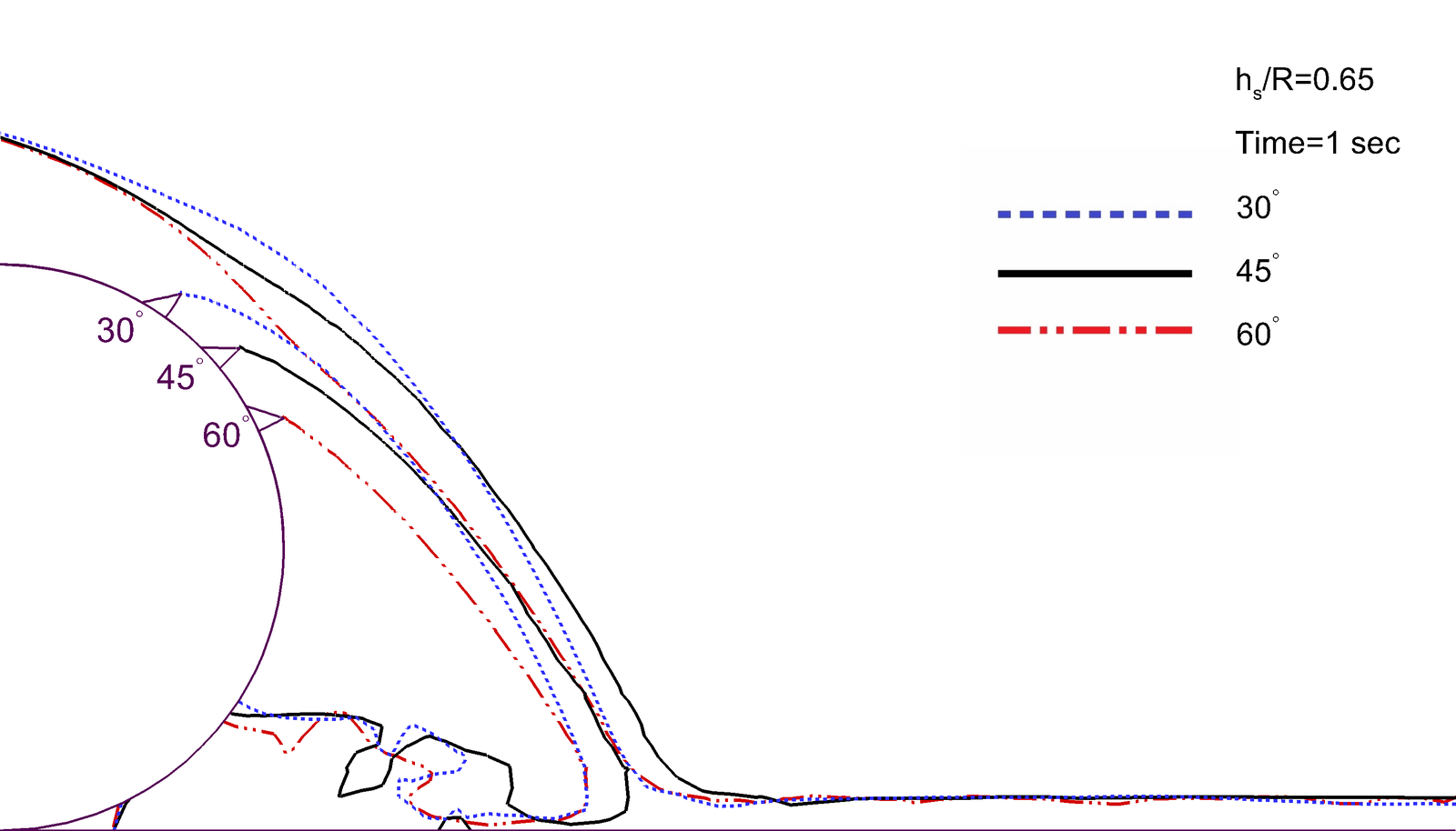
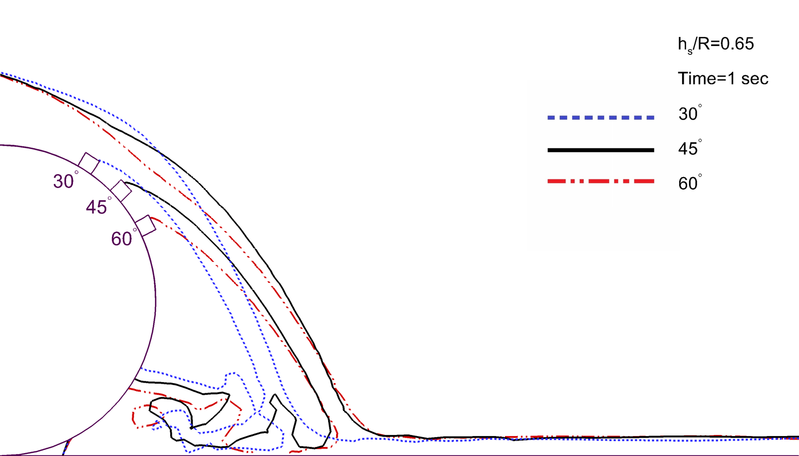
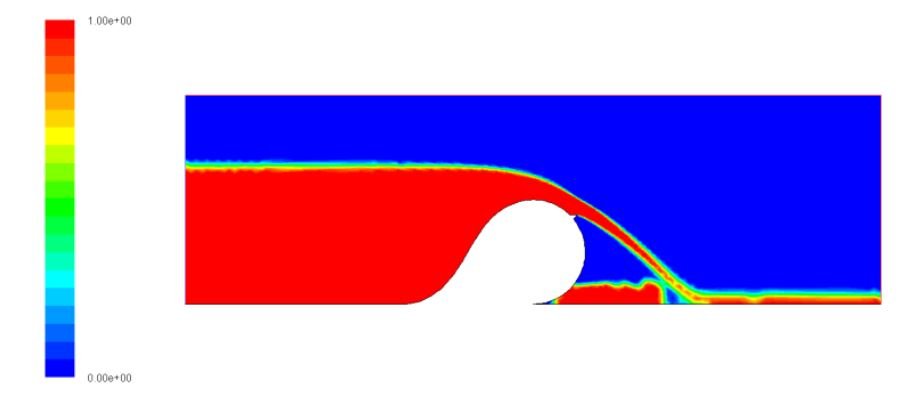
A two-dimensional transient study of incompressible water spilling over an air-inflated rubber dam, aimed at optimizing the geometry and installation angle of a downstream flow deflector — maximizing the free-jet throw length while minimizing flow-induced structural vibration and wall erosion. Geometry is meshed in Gambit and solved in ANSYS Fluent; the air–water interface is captured with the Volume of Fluid (VOF) method with geometric reconstruction, turbulence is closed with standard k-ε and RNG models, and surface tension enters through the Continuum Surface Force formulation. The inflated dam's own shape is validated against Anwar's hydrostatic equation, and the predicted jet throw length is checked against both Chanson's analytical correlation and Sorouri-Nezhad et al.'s experimental correlation. A dimensionless cavitation parameter (σ) monitors structural risk.
  • Model & validation: the inflated dam shape is derived from Anwar's hydrostatic equation, and the CFD jet throw length matches both Chanson's analytical correlation and Sorouri-Nezhad et al.'s experimental correlation to within 3.4% across hs/R = 0.4–0.65.
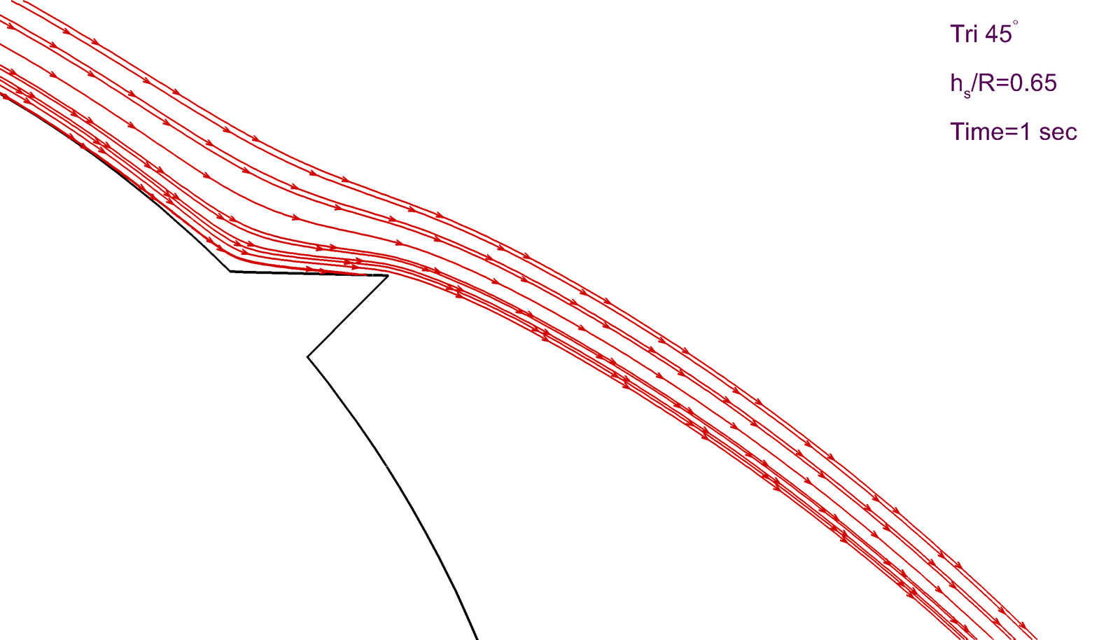
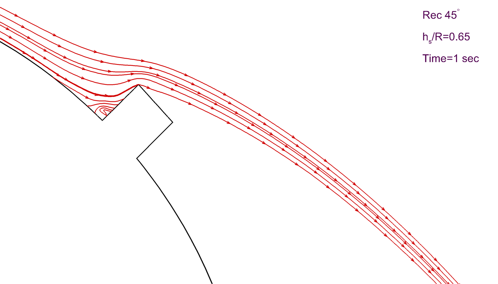
  • Deflector geometry: streamlines stay smooth and attached over the triangular deflector, while the rectangular block traps a small recirculation vortex in the corner behind its vertical face — the source of the extra flow-induced vibration and wall wear it causes.
  • Optimal angle: a 45° installation maximizes jet throw length versus 30° (premature nappe re-attachment) and 60° (excessive vertical deflection); at low flow (hs/R = 0.2) only the 30° deflector loses separation and lets the jet fall back onto the dam wall.
  • Structural safety: the cavitation indicator (σ) never lets the local pressure drop below the 3.17 kPa vapor-pressure threshold at 25°C, across every deflector shape, angle, and flow rate tested — zero predicted risk of cavitation erosion.
Turbulent Mixing · Sliding-Mesh CFD

Three-Dimensional Turbulent Flow in an Agitated Mixing Tank

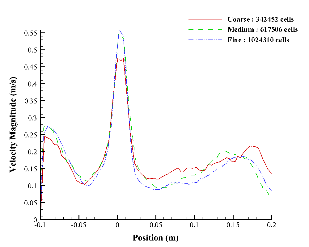
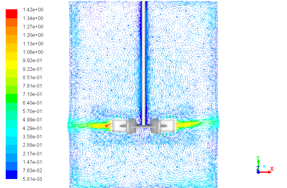
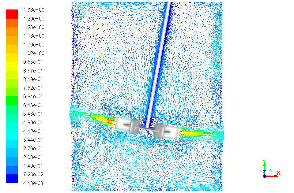
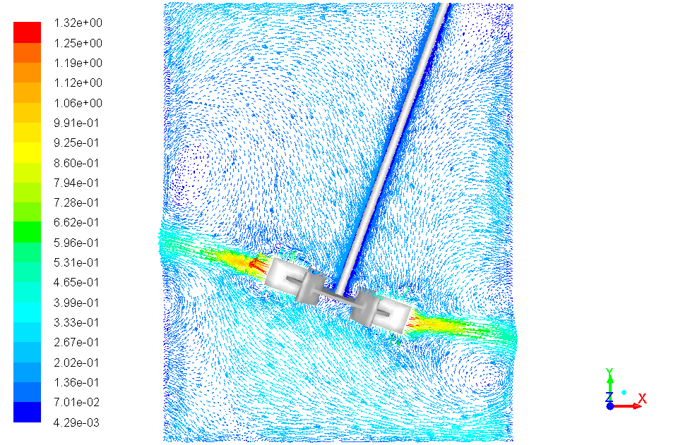
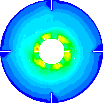
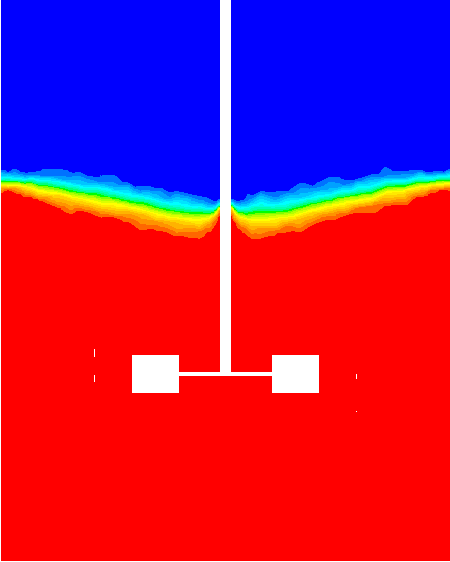
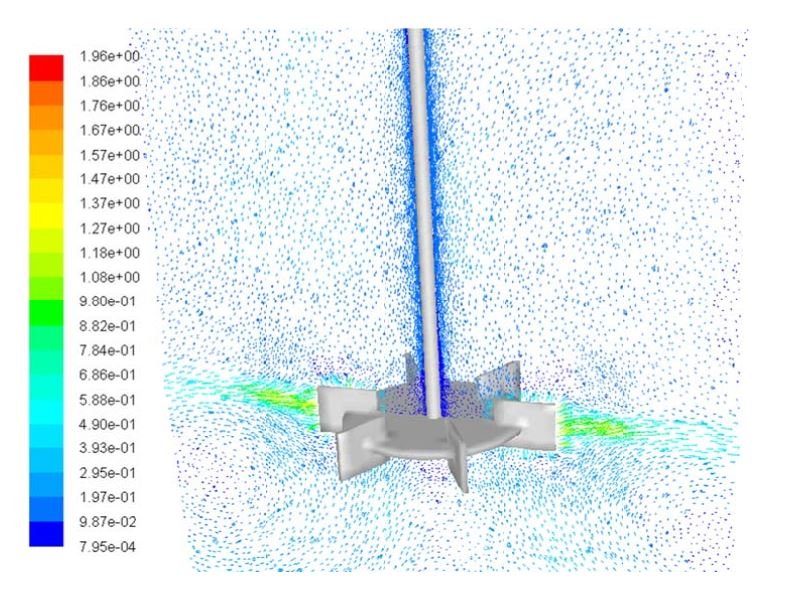
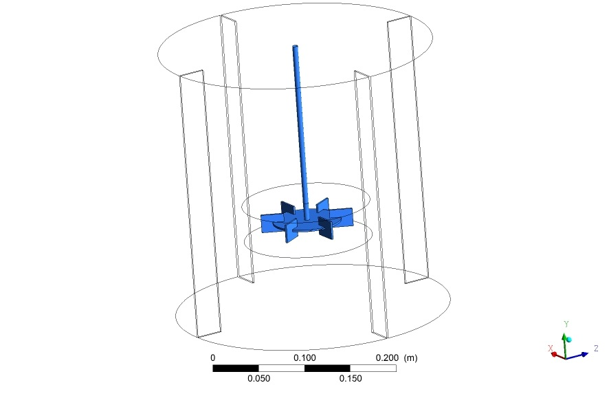
A transient, three-dimensional study of the isothermal turbulent flow inside a cylindrical mixing tank (T = 300 mm, four wall baffles) driven by a standard six-blade Rushton turbine at 250 rpm. Geometry is built in SolidWorks, meshed with Gambit, and solved in ANSYS Fluent with the impeller rotation captured by the Sliding Mesh technique — a fully transient method that resolves the blade-baffle interaction directly, rather than approximating it the way steady Multiple-Reference-Frame models do. The single-phase field is governed by the incompressible Navier–Stokes equations closed with the standard k-ε turbulence model; the water–oil configuration uses an Eulerian–Eulerian two-fluid framework with inter-phase momentum exchange dominated by drag, closed via the Schiller–Naumann model. Before the parametric study begins, the CFD model is checked for grid independence and validated on three independent fronts against published experimental and numerical data.
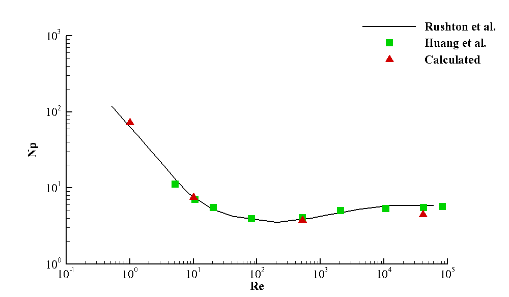
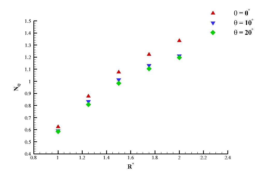
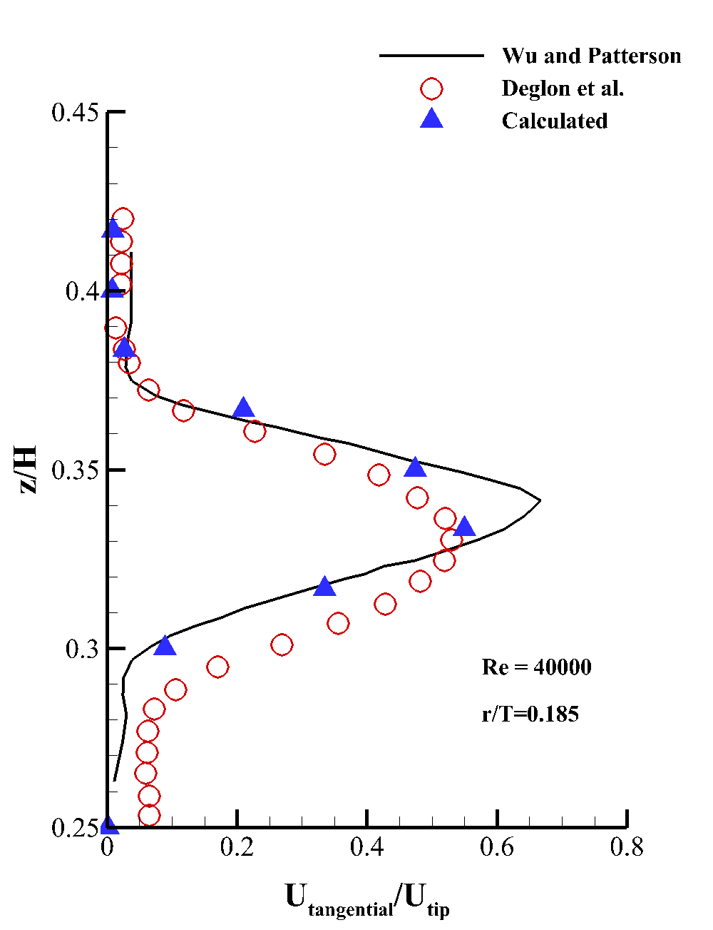
  • Model & validation: mesh-independence (three grids, 342k–1.02M cells) and near-wall y+ (30–300) checks precede validation against literature on three fronts — power number vs. Rushton et al. and Huang & Li across Re = 1–100,000, pump number vs. published correlations, and near-blade tangential velocity vs. Wu & Patterson and Deglon et al. at Re = 40,000 — all in close agreement.
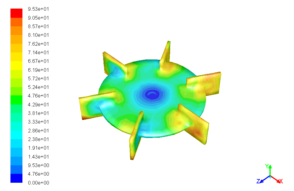
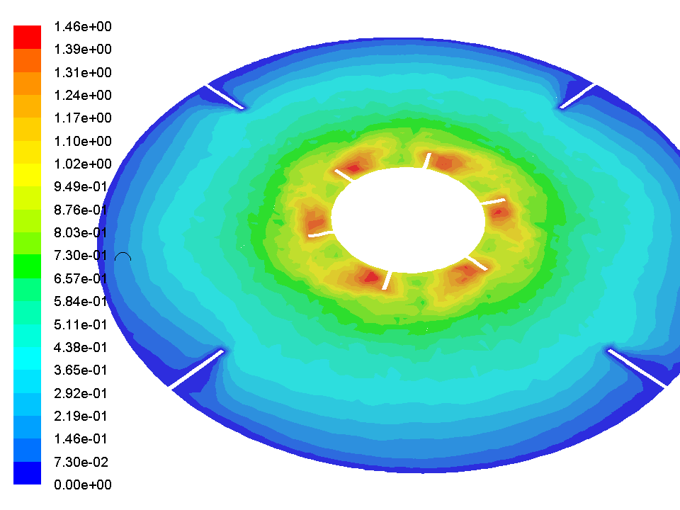
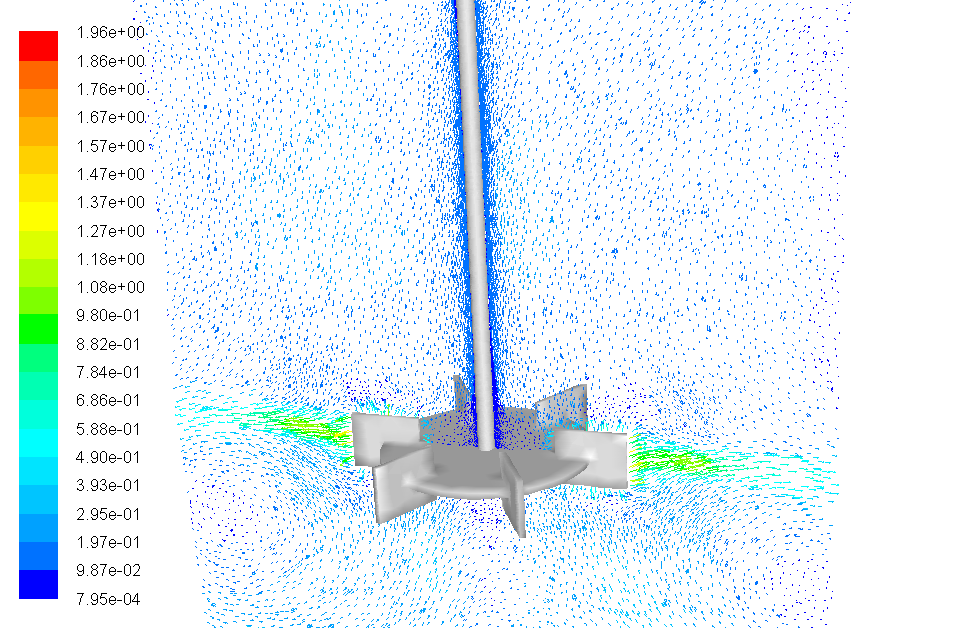
  • Dead-zone reduction: tilting the impeller blades raises velocity magnitudes throughout the vessel, driving stagnant peripheral fluid back into the high-shear impeller stream and boosting macro-mixing efficiency.
  • Power vs. pumping: the power number stays nearly constant with blade angle (Np = 4.02 at 0° vs. 3.98 at 20°), while the pumping capacity coefficient drops at larger radial distances from the hub — a clean efficiency trade-off.
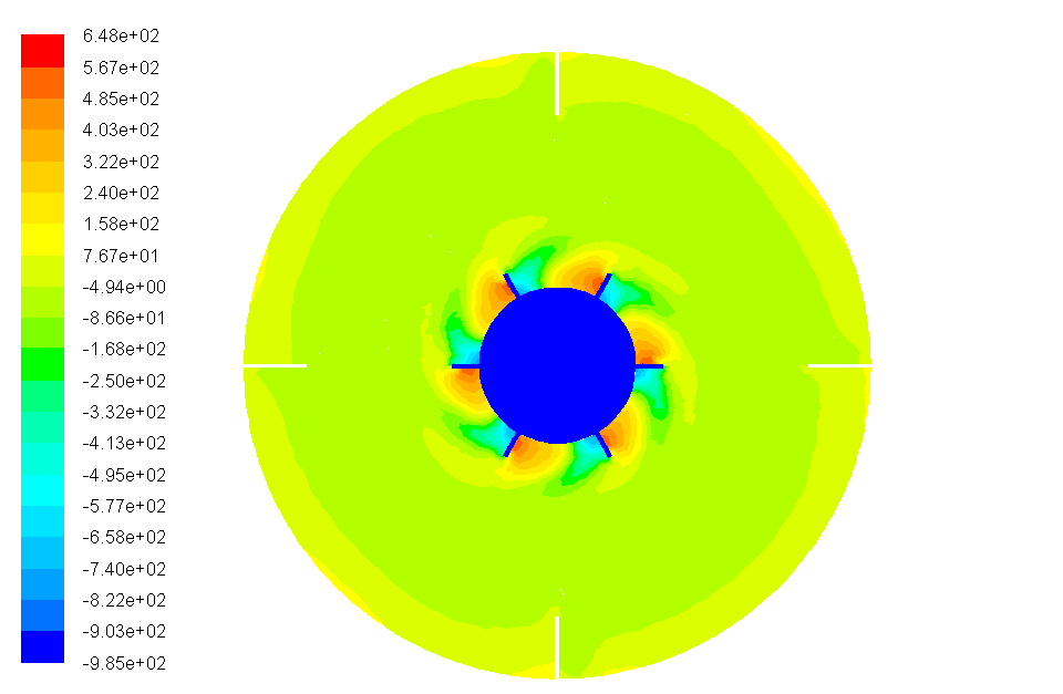
  • Flow structure: a trailing-vortex pair forms behind each blade, static pressure peaks on the blades' leading faces and drops behind them, and turbulent kinetic energy and dissipation both peak along the outer blade edges before diffusing toward the tank walls.
Turbomachinery Design · Geometric & Potential-Flow Methods

Design and Simulation of Kaplan and Francis Turbine Runners

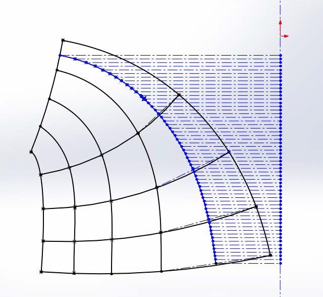
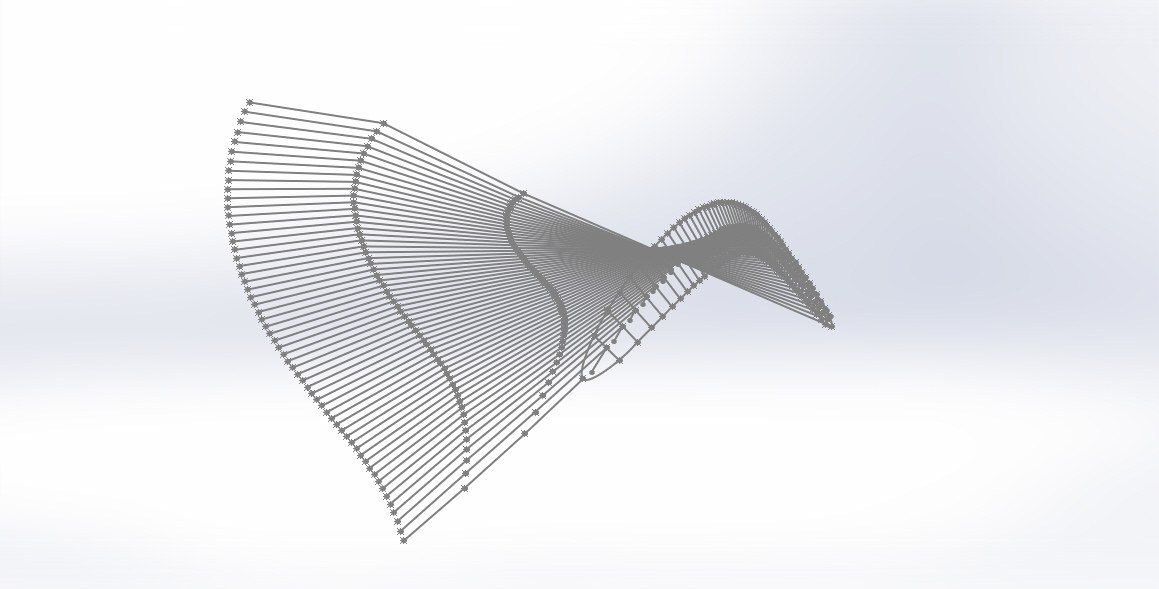
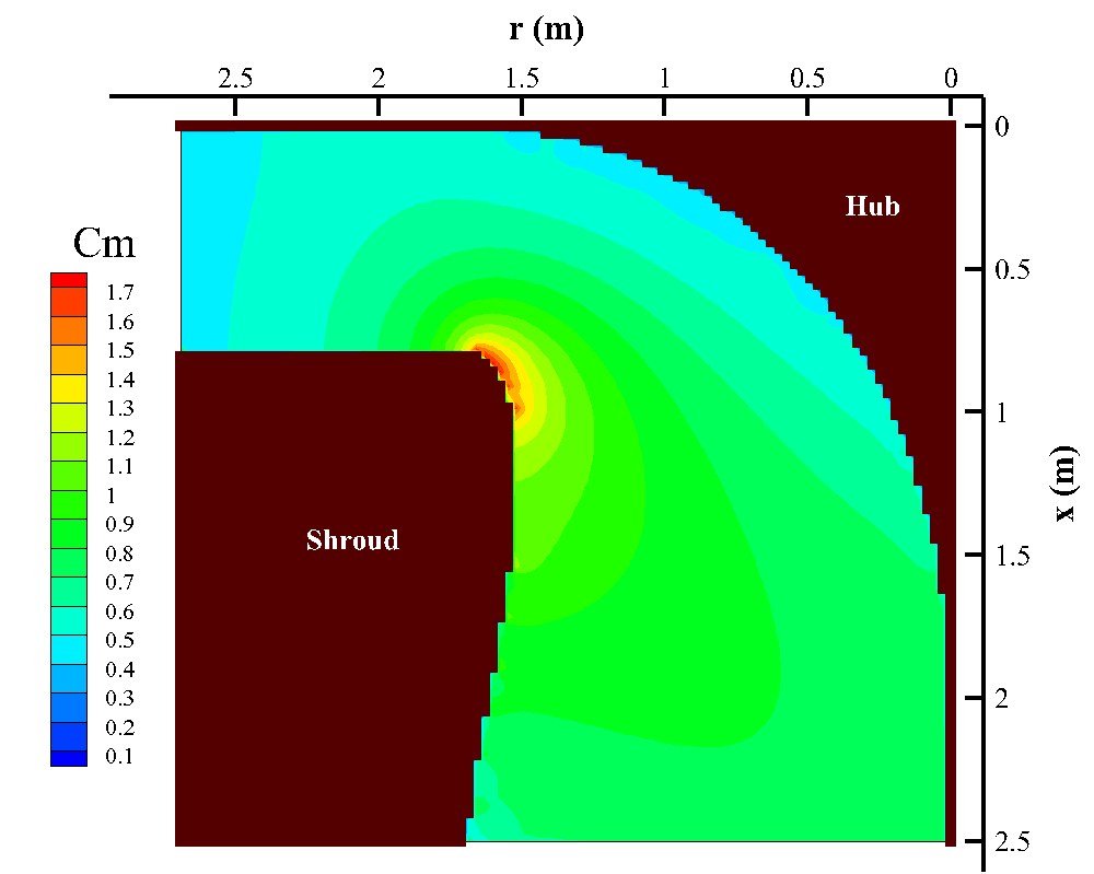
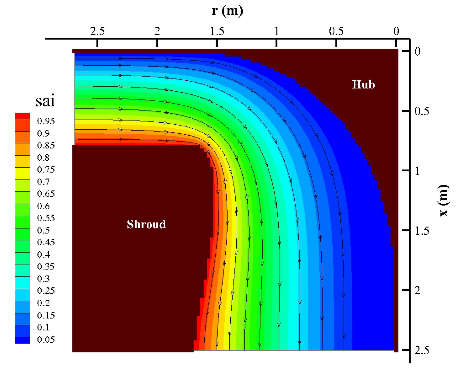
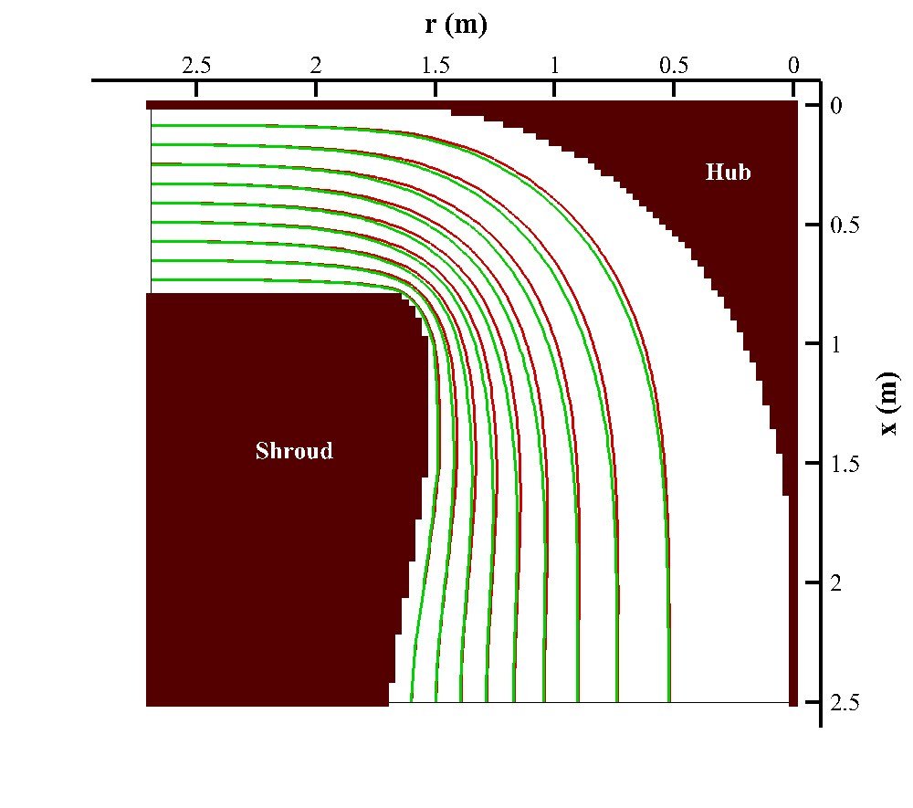
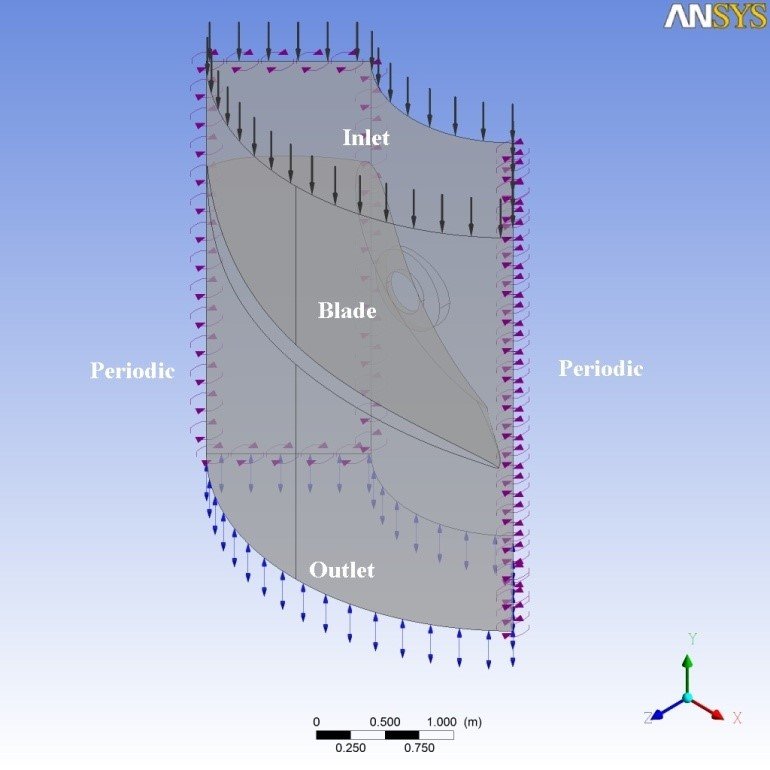
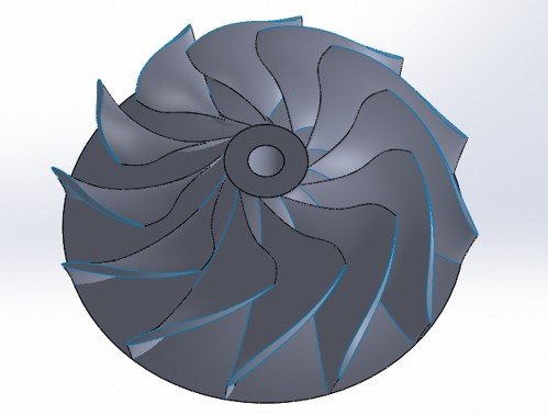
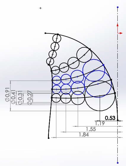
A comparative runner-design study for two classical reaction turbines. The Kaplan runner is sized from head, flow rate, and specific-speed similarity (de Leva–de Siervo correlations), with blade angles refined via Carter's deviation rule and NACA compressor-cascade correlations across five streamlines, then meshed as a single-blade periodic domain and solved in ANSYS CFX (k-ε) to check the resulting pressure and blade-loading distributions. The Francis runner blade surface is derived two independent ways for cross-validation: a graphical hub-to-shroud streamline construction (inscribed circles, conformally mapped into 3D across roughly 60 angular stations per blade passage), and a numerical solution of the meridional stream-function equation — including the guide-vane exit swirl — on the meridional plane (finite-difference, SOR).
  • Kaplan runner: sized from a 40.5 m head and 105 m³/s flow rate for a 39 MW design output at 166.67 rpm (specific speed Ns ≈ 370) — a 4-blade runner spanning a 4.47 m tip to 2.26 m hub diameter.
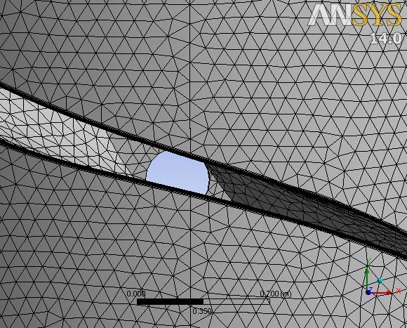
  • Kaplan CFD validation: a single-blade periodic domain in ANSYS CFX (k-ε, 10-layer inflation mesh) predicts 45.1 MW at an effective 46.3 m head — about 87% of the 51.3 MW shaft-power target once generator and mechanical losses are included.
  • Francis runner: sized from a 114 m head and 154 m³/s flow rate for a 163.3 MW design output at 187.5 rpm (Ns ≈ 203) — inlet/outlet diameters of 3.61 m / 3.37 m from standard Francis coefficient charts, yielding a 12-blade runner.
  • Cross-validated geometry: the graphical streamline construction and the swirl-corrected stream-function solution converge on the same Francis runner shape — even comparing the stream function with and without guide-vane swirl shows only a small shift in the meridional streamlines, confirming the flow field used to derive the blade surface.
CO2 Sequestration · Reservoir Simulation

Optimal Well Placement and Injection Strategy for CO2 Sequestration

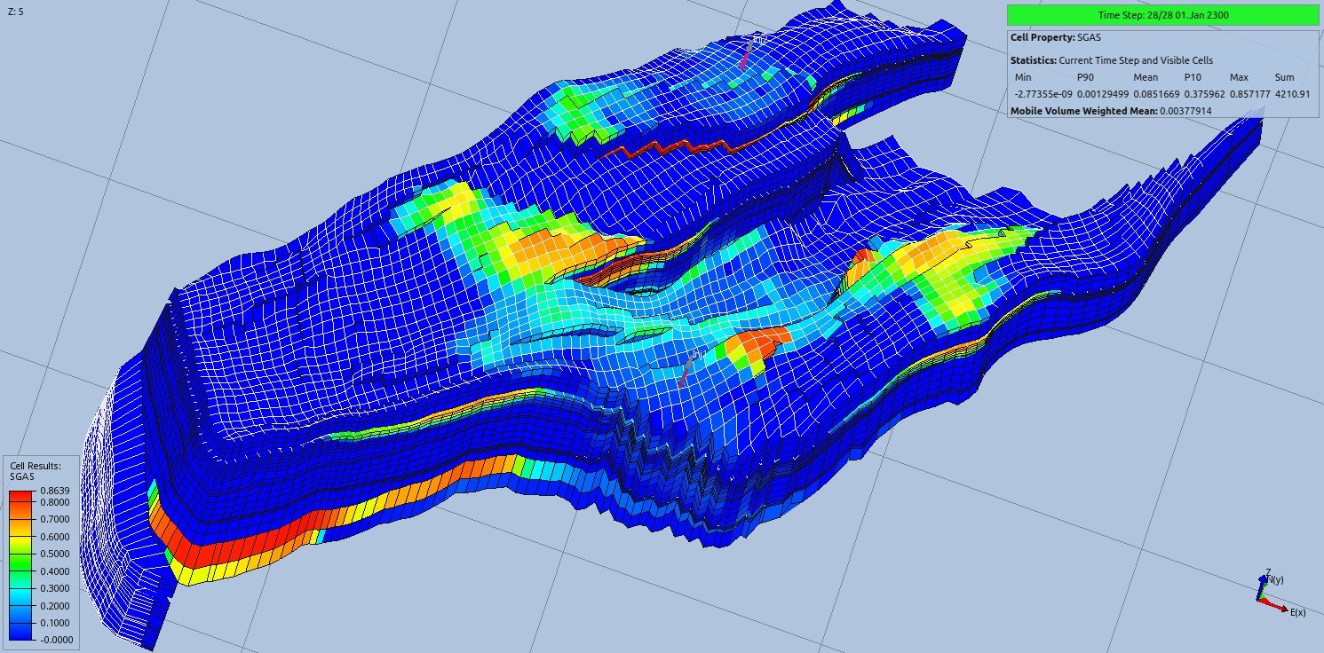
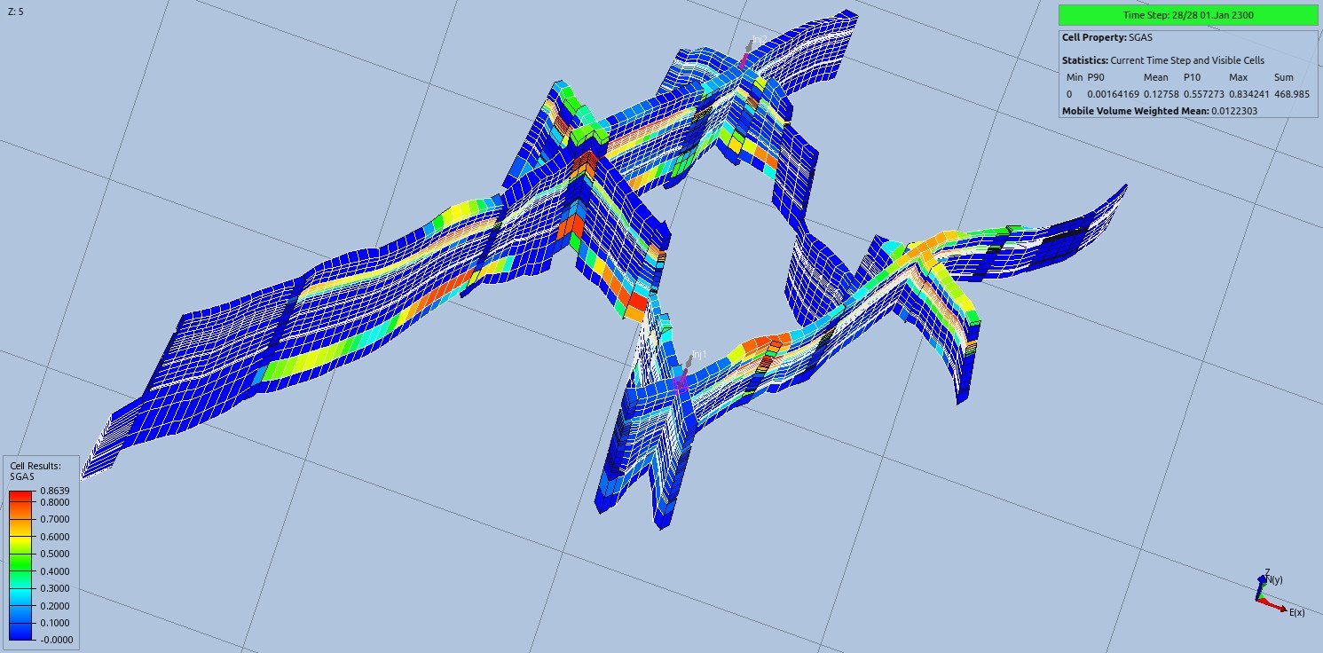
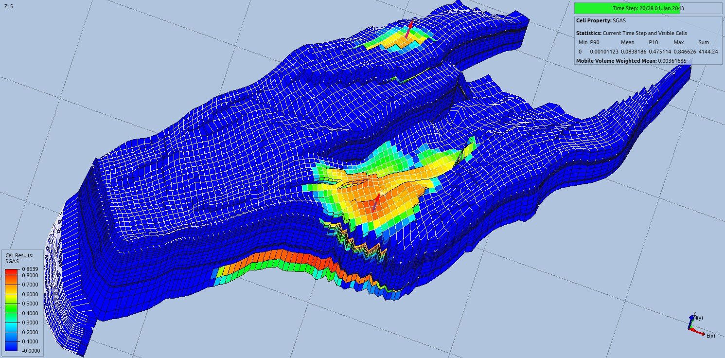
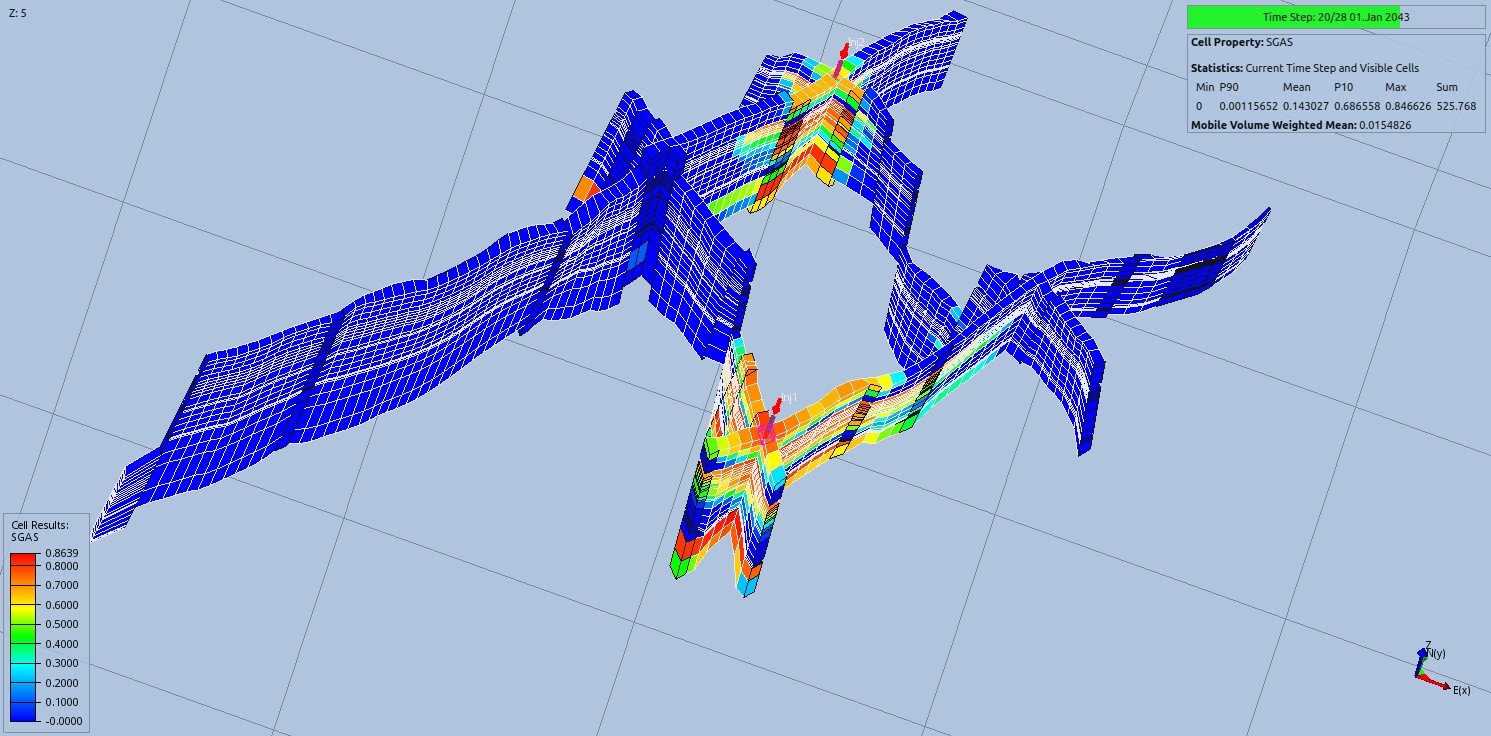
A well-placement optimization study for CO2 storage in a saline aquifer, using a synthetic case built on the Norne field's geology (Norwegian Sea). OPM Flow's dedicated CO2STORE module computes CO2 PVT properties — density, viscosity, enthalpy — from analytic correlations and converts them to black-oil equivalents internally, giving compositional-simulator accuracy at black-oil performance; results are visualized and quantified in ResInsight. Injection layouts with 1 to 5 wells at different grid positions are screened against a fixed injection schedule and a 350 bar per-well pressure limit, tracking how much CO2 stays trapped in the field versus migrates into the neighboring aquifers.
  • Reservoir case: horst-block saline aquifer, ∼9 × 3 km, sandstone at 2500–2700 m depth, 25–30% porosity, 20–2500 mD permeability across 17 reservoir zones — about 27.74 billion Sm³ of CO2 injected over the operating life.
  • Optimization sweep: 1 to 5 injectors at varying (I, J) positions, ranking layouts by the CO2 mass held in the field versus the two neighboring aquifers 257 years after injection ends (January 2300).
  • Optimal layout: storage capacity per well plateaus at two injectors (≈12.2 billion Sm³/well in the field region) — additional wells add little extra capacity, so the reference case settles on a 2-injector layout.
Iterative & Krylov Solvers · Heat Conduction CFD

Heat Conduction on Structured and Unstructured Meshes: Explicit and Implicit Solvers

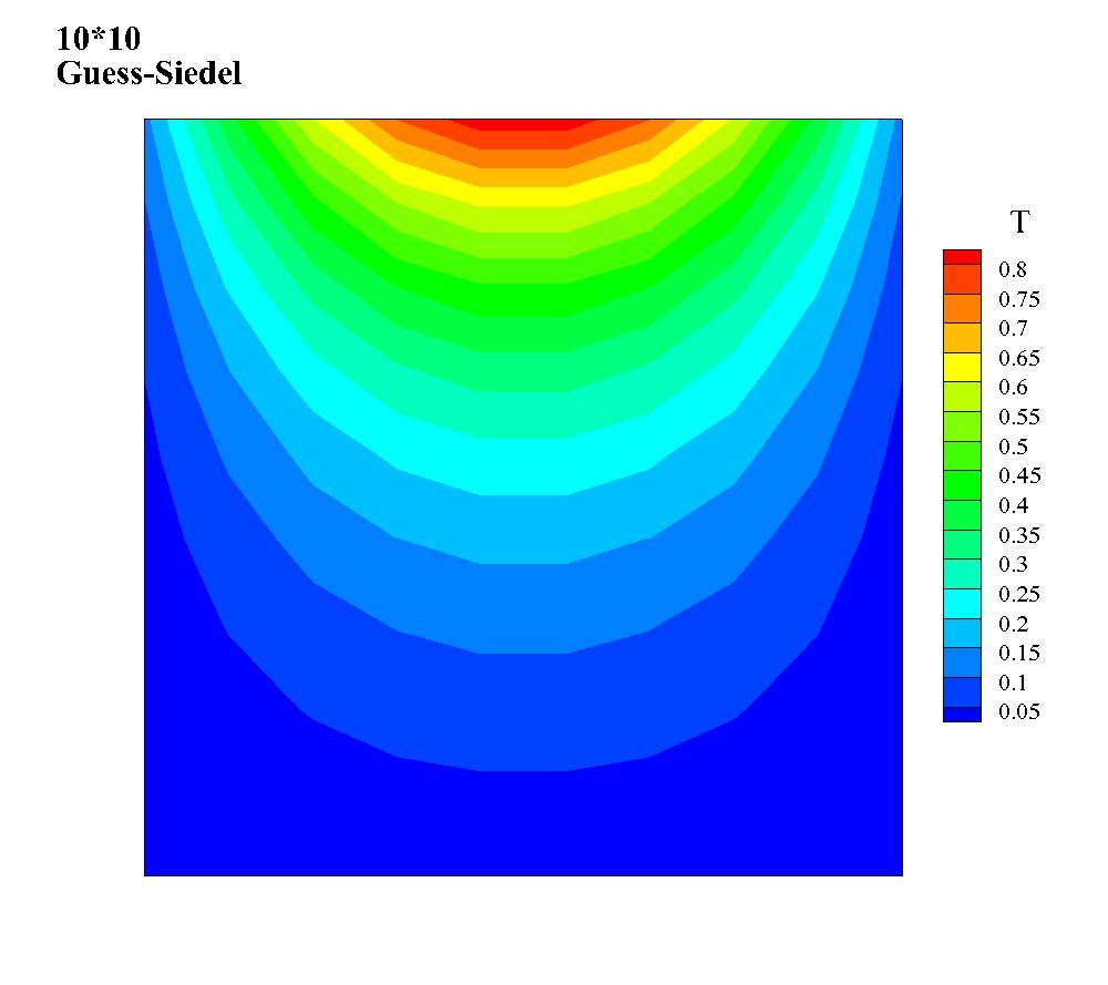
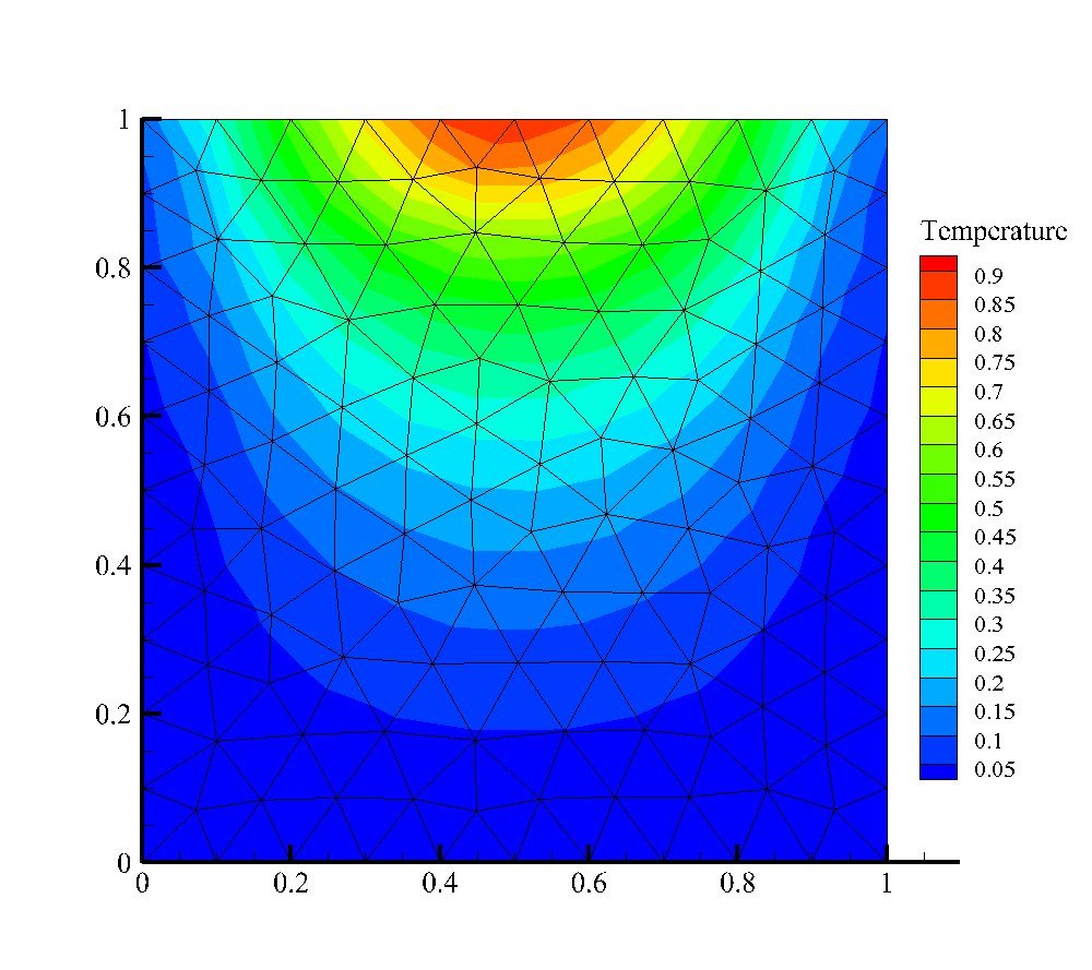
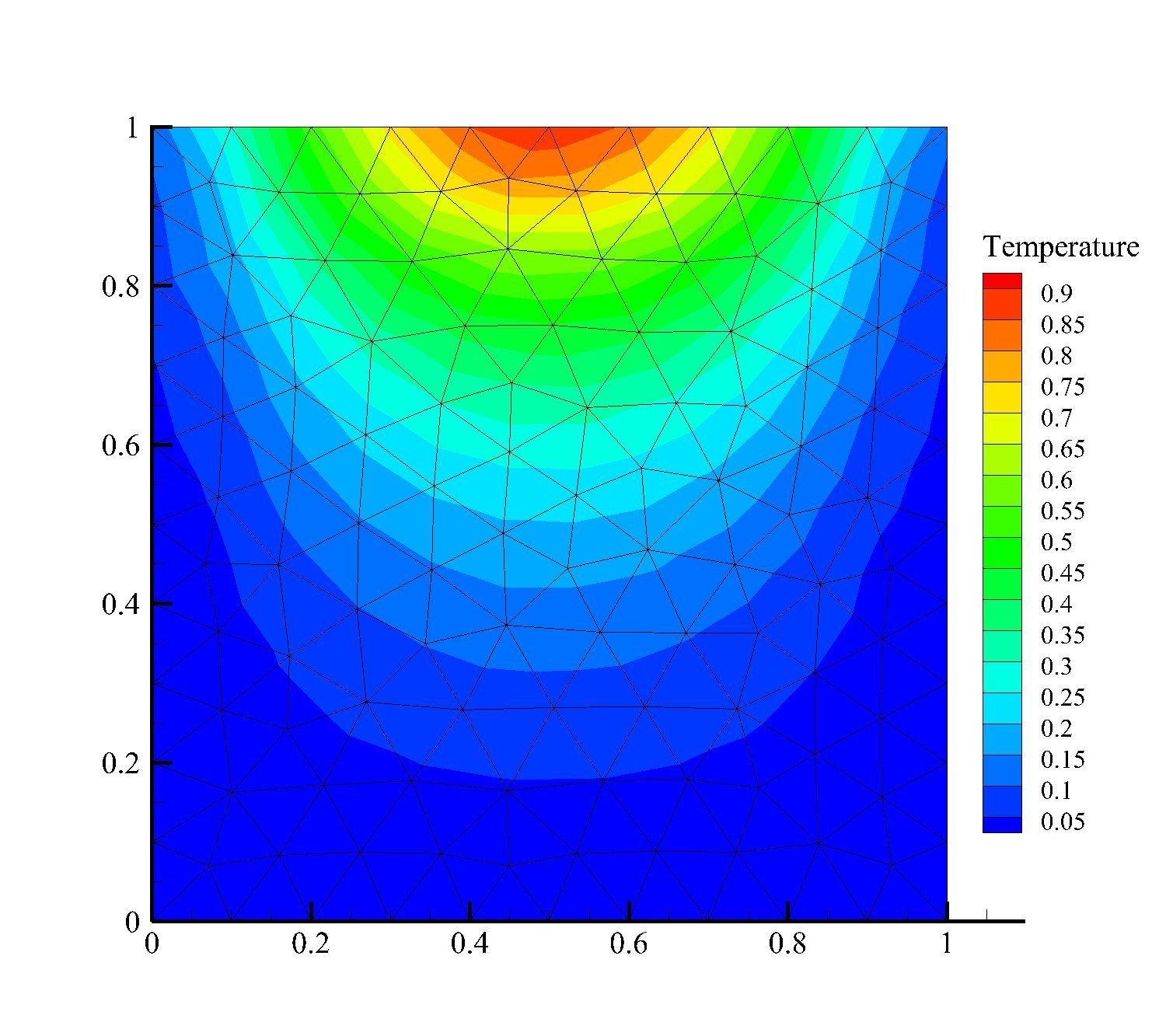
A numerical-methods study of steady two-dimensional heat conduction on a unit square with a sinusoidal Dirichlet condition on one edge, solved on both structured finite-volume grids and Gambit-generated unstructured triangular grids to compare mesh types under an identical discretization. Two explicit relaxation schemes (Gauss-Seidel and SOR) and two implicit Krylov-subspace solvers (GMRES and BiCGSTAB) are implemented in Fortran 90, with the implicit Jacobian built matrix-free via finite-difference perturbation and stored in Compressed Row Storage; Reverse Cuthill-McKee reordering shrinks the sparse bandwidth on the unstructured mesh, and SOR/ILU(0) preconditioning is benchmarked against the unpreconditioned baseline.
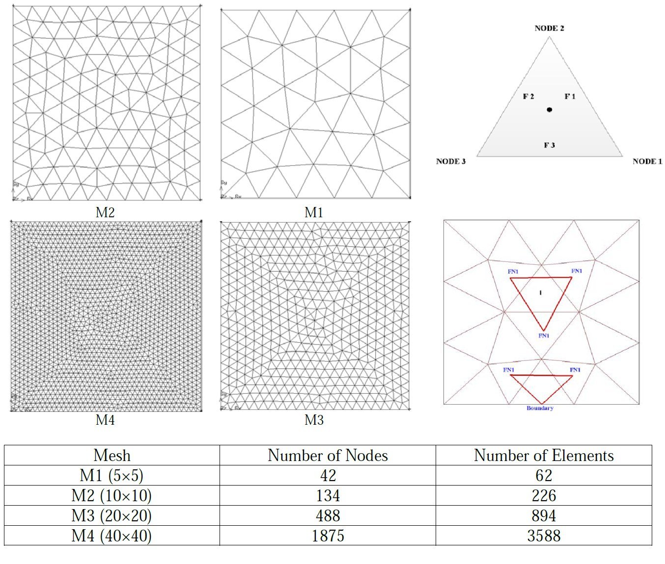
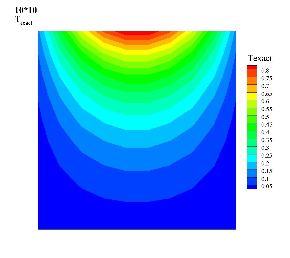
  • Problem & meshes: steady 2D conduction on a unit square (Dirichlet BCs, one edge driven by T = sin(πx)) discretized with a finite-volume Green-Gauss scheme on four structured grids (10×10 to 40×40) and four unstructured triangular grids (42 to 1,875 nodes), each checked against the closed-form solution T = sin(πx)sinh(πy)/sinh(π).
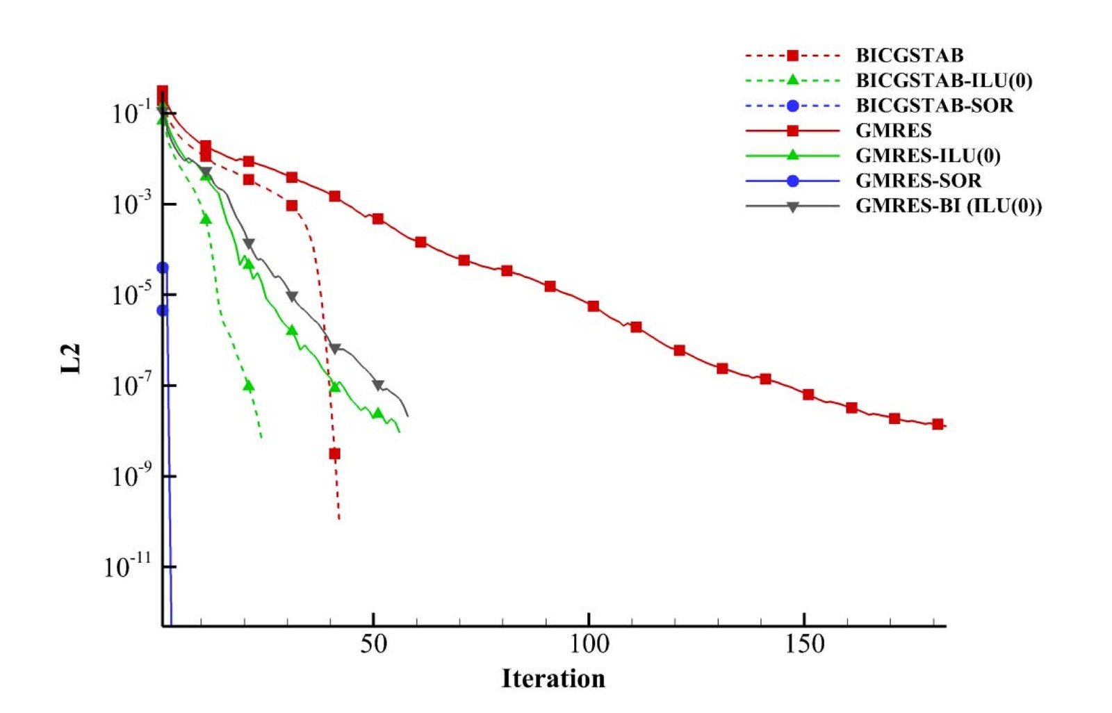
  • Explicit vs. implicit: Gauss-Seidel and SOR (ω up to 1.5) solve the discretized system by relaxation, while a matrix-free Newton-Krylov formulation builds the Jacobian by finite-difference perturbation and solves it with GMRES and BiCGSTAB on a CRS-sparse system reordered with RCM to shrink bandwidth.
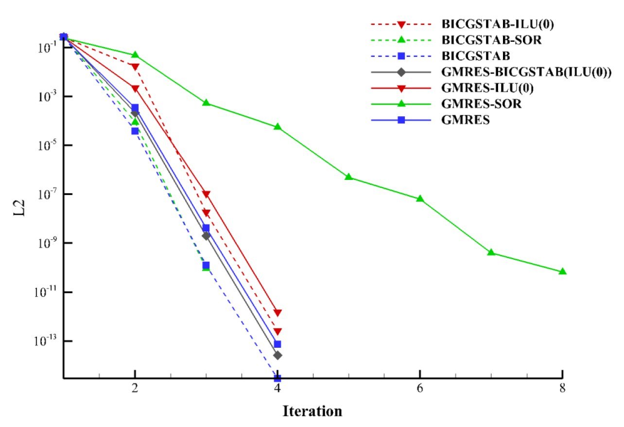
  • Preconditioning payoff: unpreconditioned GMRES/BiCGSTAB need on the order of 40–190 iterations to converge on a 900-cell mesh; adding an SOR or ILU(0) preconditioner collapses that to single digits, while both mesh types confirm second-order spatial accuracy (L1/L2/L error slopes ≈ 1.9–2.0).
Turbomachinery Design · Centrifugal Pump Design

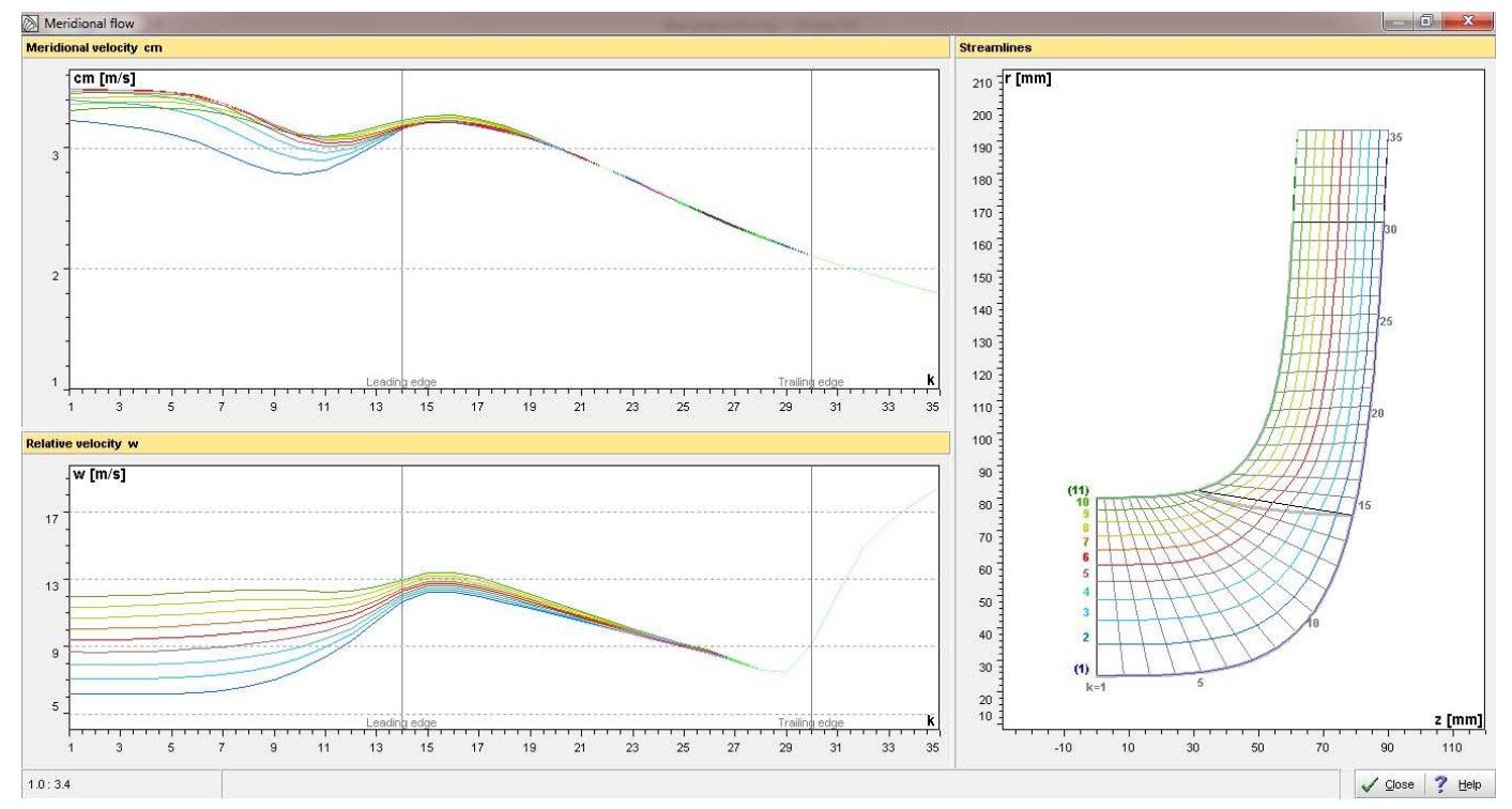
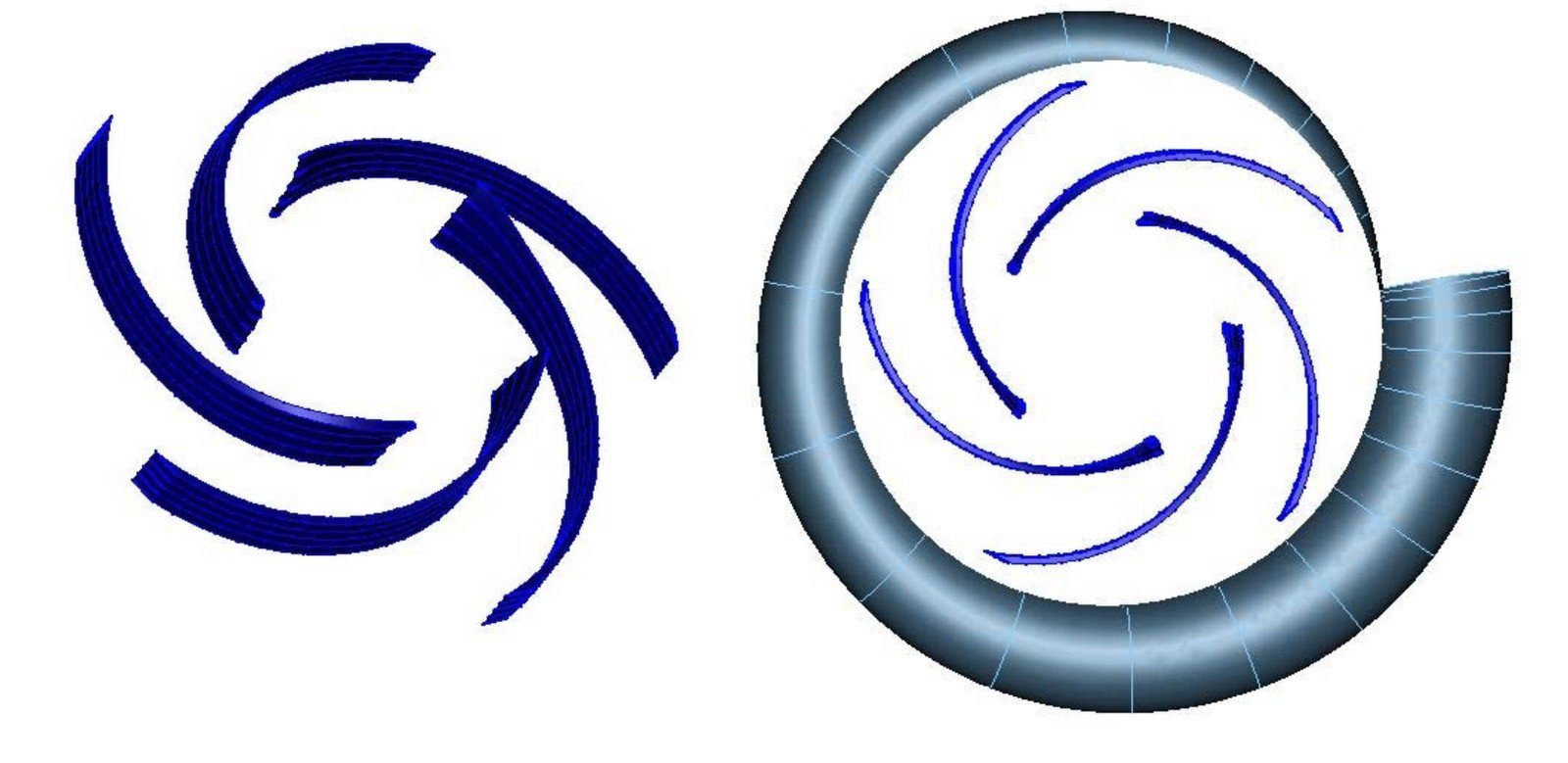
Design of a Centrifugal Pump Impeller and Volute Casing

A first-principles design of a single-stage, single-suction centrifugal pump — impeller blades and volute casing — sized from head, flow rate, and speed using the correlations in Gülich's Centrifugal Pumps and cross-checked against Lobanov/Stepanov design charts. The meridional half-section and blade geometry are built up analytically (impeller eye and outlet diameters via two independent methods, blade angles from inlet/outlet velocity triangles, blade surface unrolled by Kaplan's conformal-mapping construction) and modeled in CATIA and EES, then the same input parameters are fed into CF Turbo to regenerate the impeller and volute independently — its meridional section, velocity distributions, and 3D geometry closely match the hand-derived design, validating the analytical procedure.
  • Design point: Q = 220 m³/h (0.061 m³/s), H = 29.7 m at n = 1450 rpm gives a specific speed ns ≈ 28.2 and an estimated overall/hydraulic efficiency of 82.9%/91.1% — sizing a 5 cm shaft and a 5-blade impeller.
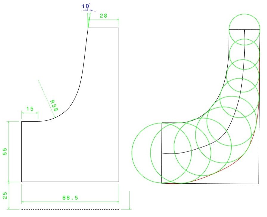
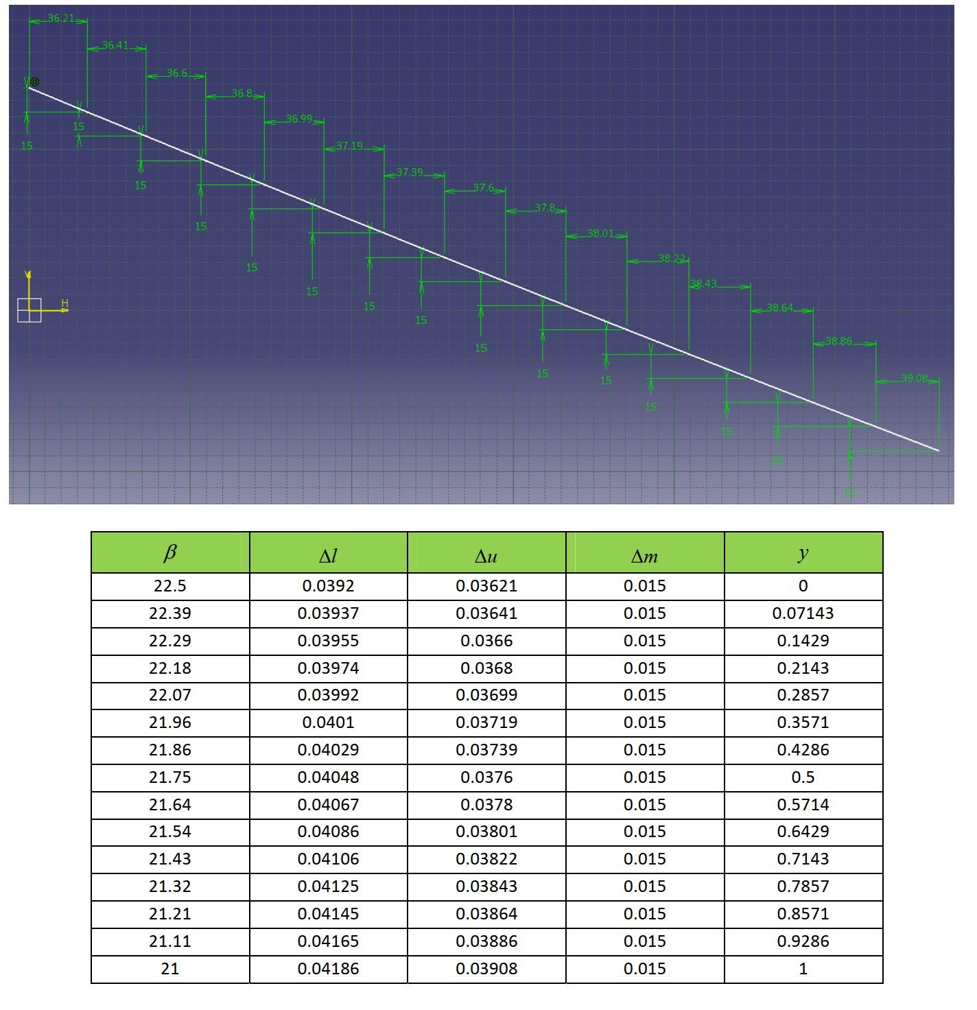
  • Impeller geometry: outlet diameter d2 = 33 cm and eye diameter d1 = 16 cm, each cross-checked with two independent correlations; blade angles of 16.3°/21° (inlet, with incidence) and 22.5° (outlet) come from the velocity triangles, with the 3D blade surface unrolled via Kaplan's conformal-mapping method across 15 hub-to-shroud stations.
  • Volute & validation: the volute cross-section is sized by the constant-mean-velocity method (area growing continuously around 360°, fit with a cubic polynomial in EES); feeding the same design point into CF Turbo reproduces a near-identical meridional section, velocity field, and 3D impeller/volute geometry, confirming the hand-calculated design.
Thermal Systems Optimization · MATLAB-GA & EES

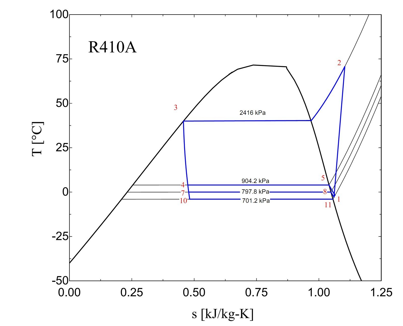
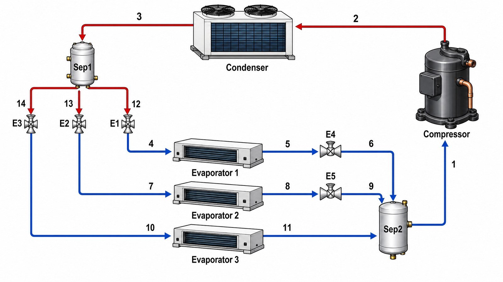
Genetic-Algorithm Optimization and Exergo-Economic Analysis of a VRF Cycle

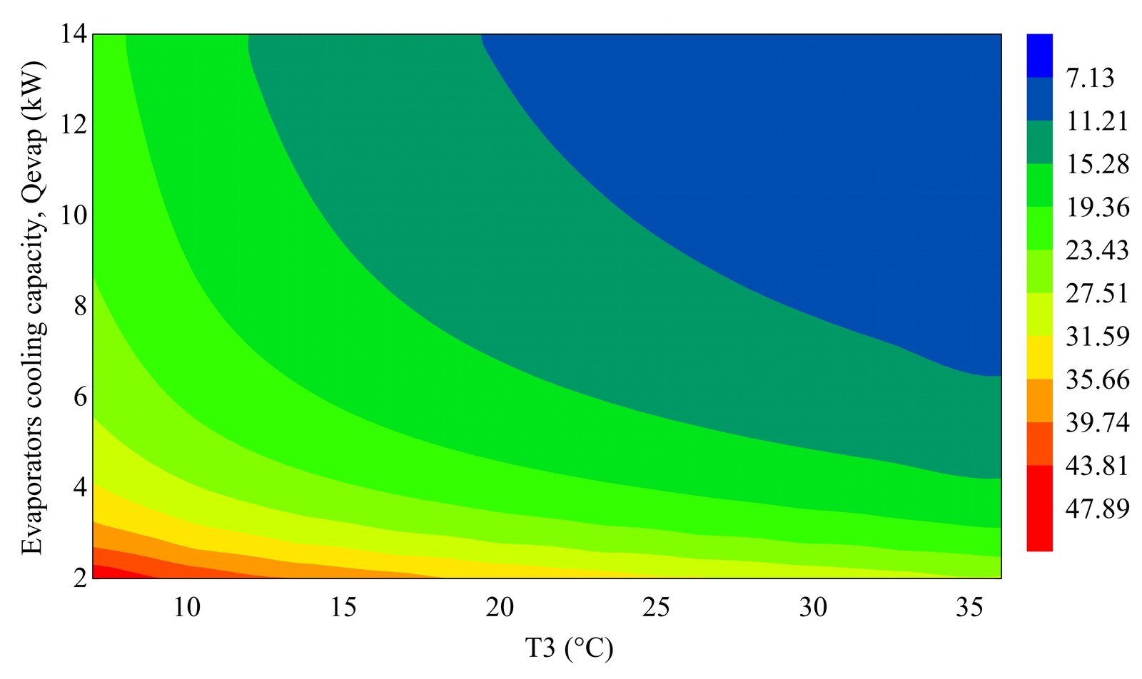
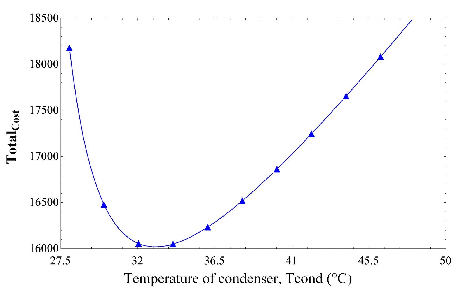
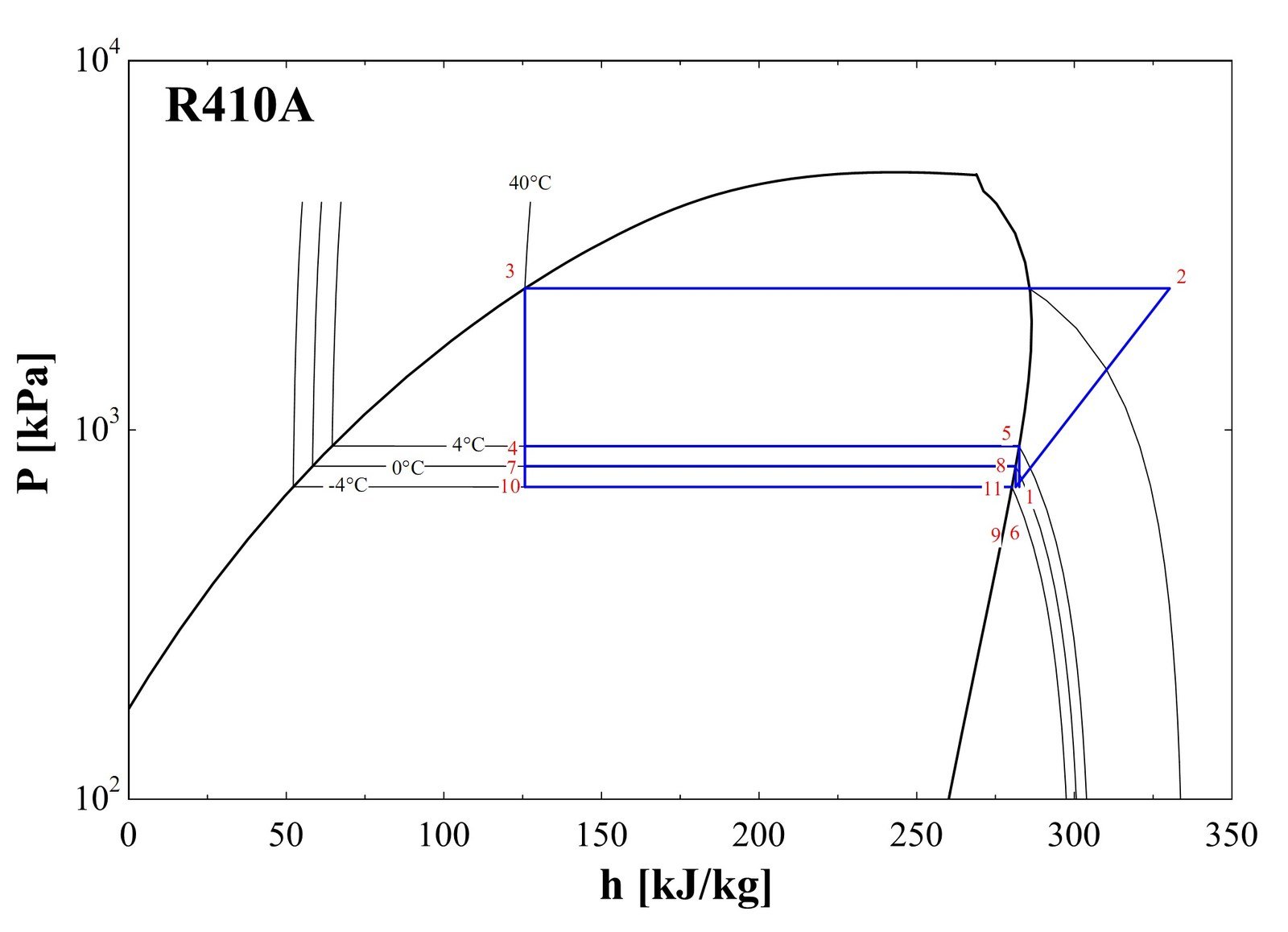
An exergy and thermoeconomic study of a three-evaporator Variable Refrigerant Flow (VRF) cooling cycle (R-410a; one compressor, one air-cooled condenser, three evaporators at 4°C/0°C/−4°C, five expansion valves, and two refrigerant separators), modeled state-by-state in EES and linked to a genetic algorithm in MATLAB. The GA searches the condenser temperature and evaporator cooling-capacity design space for the combination that jointly maximizes COP and minimizes total refrigerant mass flow; independently, an exergy balance quantifies irreversibility at every component, and an economic model — capital-cost correlations plus electricity cost — locates the condenser temperature that minimizes total annualized cost.
  • Cycle & exergy: the 3-evaporator VRF cycle reaches a second-law (exergy) efficiency of 47% — below an equivalent single-evaporator cycle's 53% — with the compressor responsible for 52% of the cycle's 6.0 kW total irreversibility and the five throttling valves accounting for most of the rest.
  • GA optimization: a population-100 genetic algorithm (85% crossover, 5% mutation, 200 generations) searches condenser temperature (7–36°C) and evaporator capacity (2–14 kW) to jointly maximize COP and minimize refrigerant mass flow, converging to the low-temperature, low-capacity corner of the design space where COP is highest and mass flow lowest.
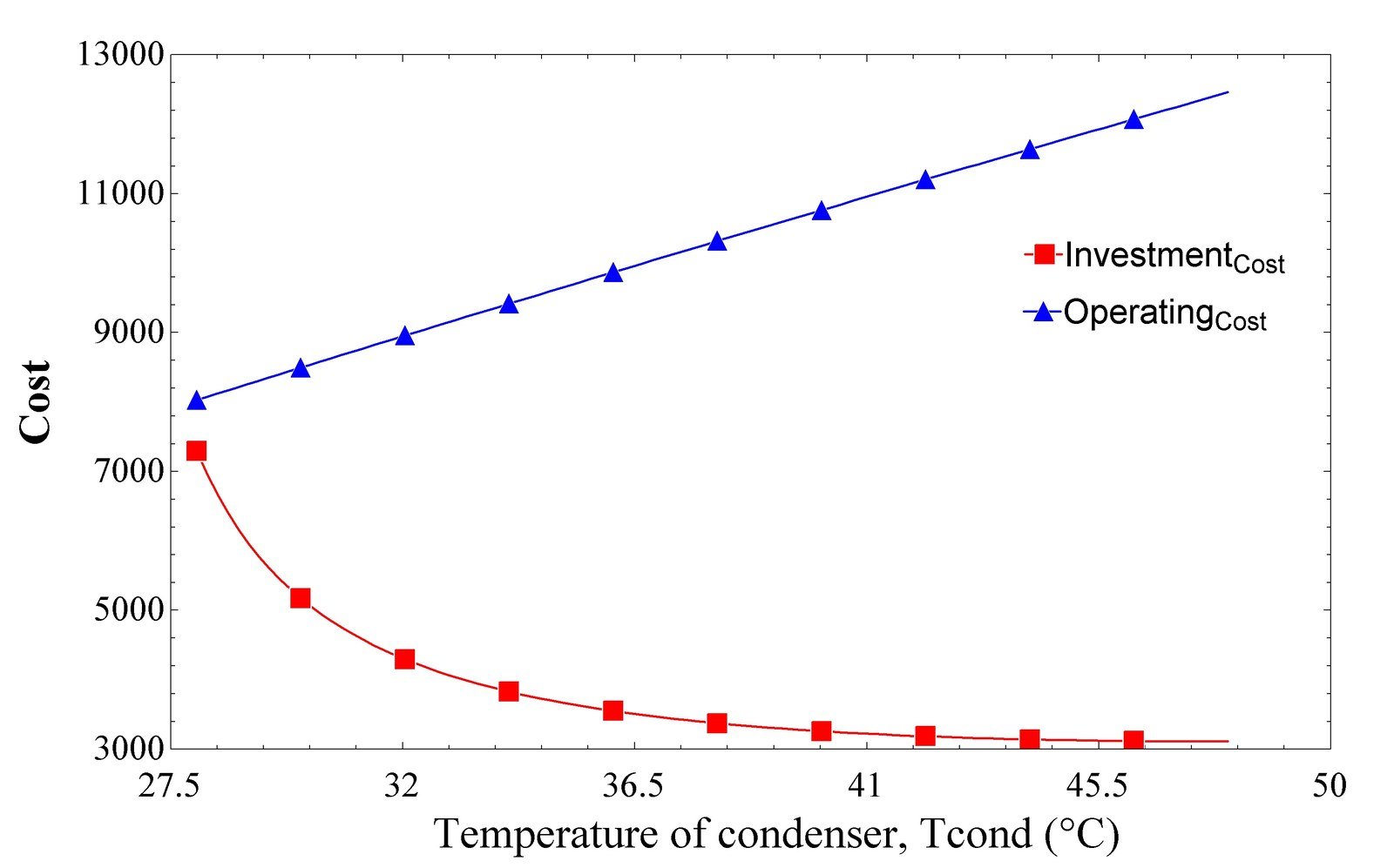
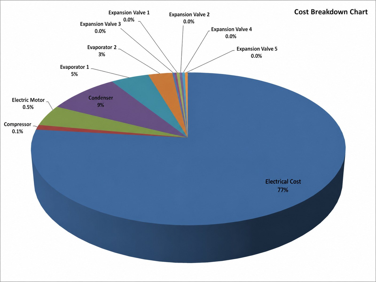
  • Economic optimum: annualized cost — electricity (≈77%) plus the capital cost of the compressor, condenser, evaporators, valves, and motor — is minimized near a condenser temperature of ≈33°C, where falling equipment cost (smaller heat-exchanger area) is offset by rising compressor and electricity cost as the condensing temperature climbs further.
Genetic-Algorithm Design Optimization · Converging-Diverging Nozzle CFD

Genetic-Algorithm and Neural-Network Optimization of a Converging-Diverging Nozzle

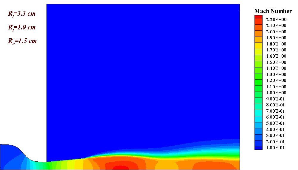
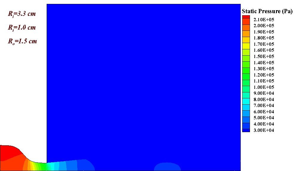
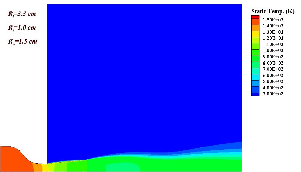
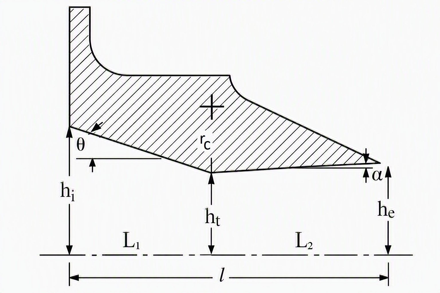
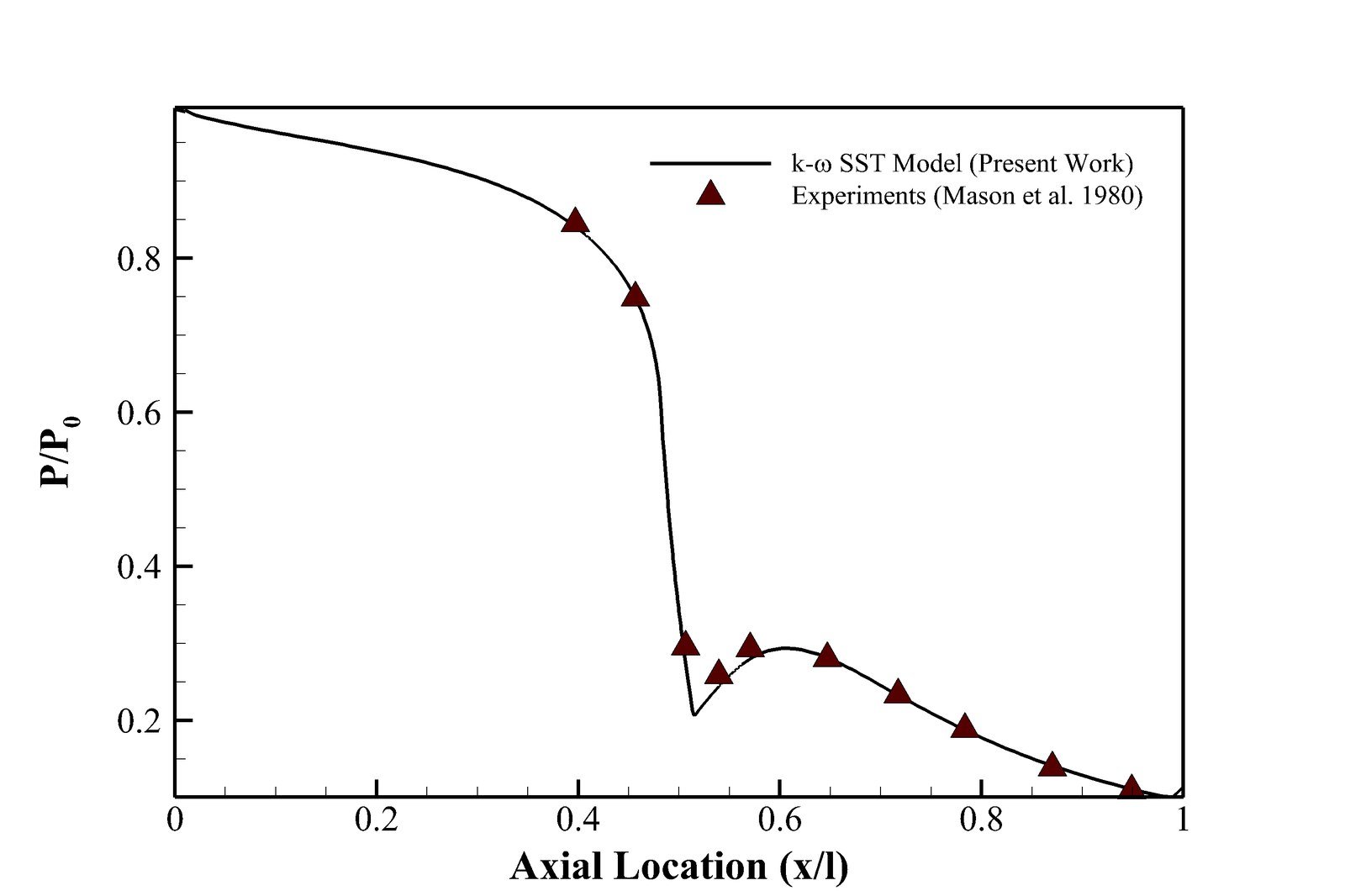
A two-dimensional, axisymmetric CFD study of the supersonic flow inside a converging-diverging nozzle, solved in ANSYS Fluent (density-based, k-ω SST) across the compressible Navier–Stokes, energy, and ideal-gas equations. Because a full CFD sweep of every candidate geometry is too slow to embed inside an optimizer, a two-layer neural network is trained on 125 Fluent cases to predict the thrust-to-weight ratio directly from three geometric parameters — inlet, throat, and outlet height — and a genetic algorithm then searches that trained surrogate for the geometry that maximizes thrust-to-weight, with the result verified by re-running it through Fluent.
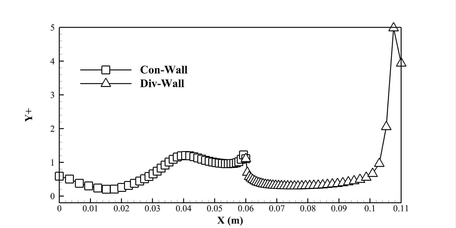
  • Setup & validation: a structured mesh (wall y+ < 1.3) is confirmed grid-independent across three densities (thrust force within 0.1%) and validated against a NASA Technical Paper (1980) throat-contouring nozzle experiment — the CFD wall-pressure distribution, including the shock structure, matches the measured data closely.
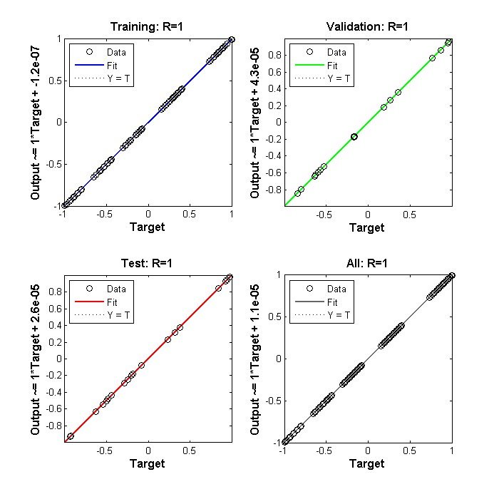
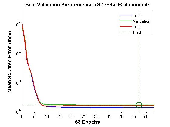
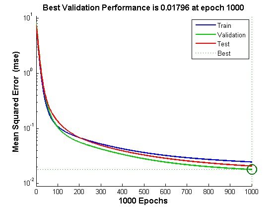
  • Neural-network surrogate: a 3-input, 10-hidden-neuron, 1-output perceptron (inlet/throat/outlet height → thrust-to-weight ratio) trained on 125 CFD cases with Levenberg-Marquardt backpropagation reaches a training MSE of 1.7×10⁻⁹ and R2 = 1 — far outperforming gradient-descent training, which stalls around MSE ≈ 0.02–0.07 even after 1,000 epochs.
  • GA-optimized geometry: searching the trained network, the genetic algorithm converges in about 55 generations to the minimum inlet height (3.1 cm) paired with the maximum throat and outlet heights (1.45 cm, 2.5 cm) — a thrust-to-weight ratio of 404.2, a 13.4% improvement over the design space's worst case, confirmed by an independent Fluent re-run of the optimized geometry.
Hydrodynamic Lubrication · Rayleigh Step Bearing CFD

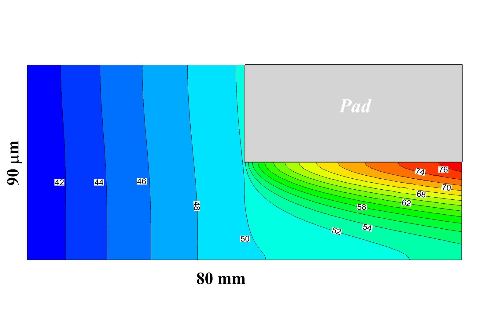
Flow and Temperature Fields in a Rayleigh Step Slider Bearing

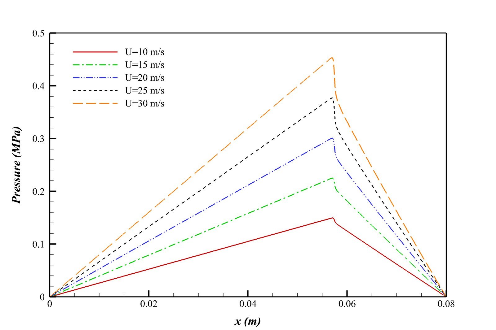
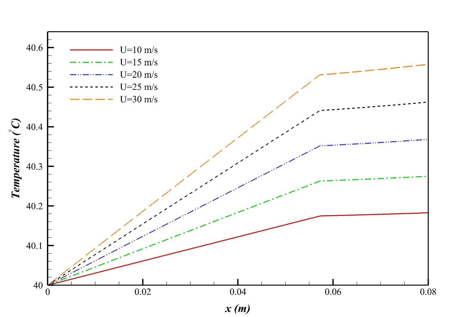
A full computational fluid dynamics study of a Rayleigh step hydrodynamic bearing — solving the coupled Navier–Stokes and energy equations directly in ANSYS Fluent, rather than the thin-film Reynolds-equation approximation classical lubrication theory relies on. Oil viscosity is coupled to temperature through a custom UDF, and the solution is validated against two independent published results before sweeping the bearing's step position, film-height ratio, runner speed, and minimum film thickness to see how each reshapes the pressure and temperature fields — and ultimately, load capacity and friction.

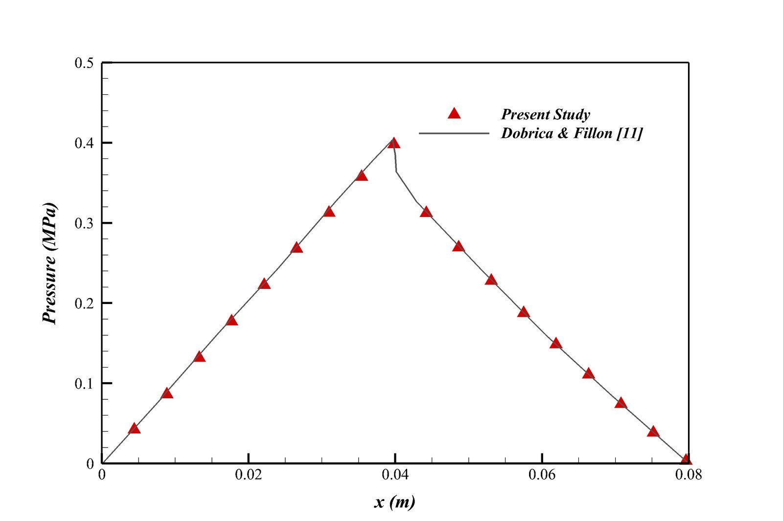
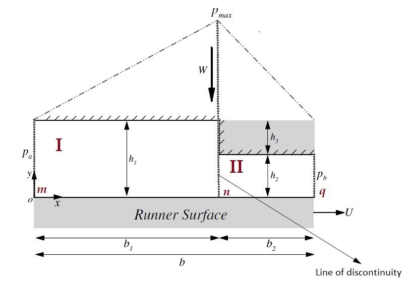
  • Method & validation: steady, incompressible Navier–Stokes and energy equations are solved on a Gambit-built mesh refined at the step's sharp gradients, with oil viscosity varying with temperature via a UDF; both the pressure distribution and the in-film temperature contours match published results (Dobrica & Fillon; Hideki) closely.
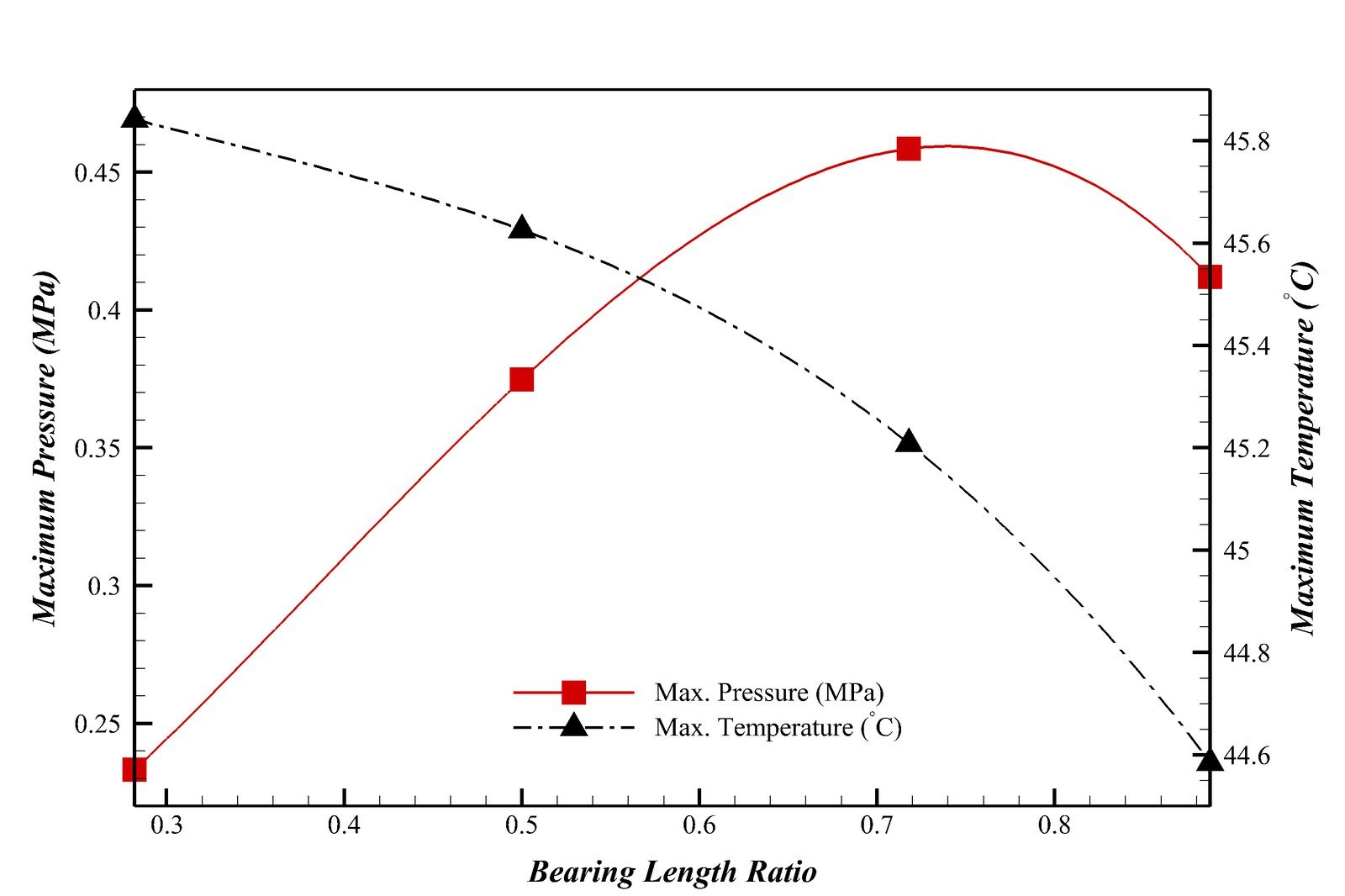
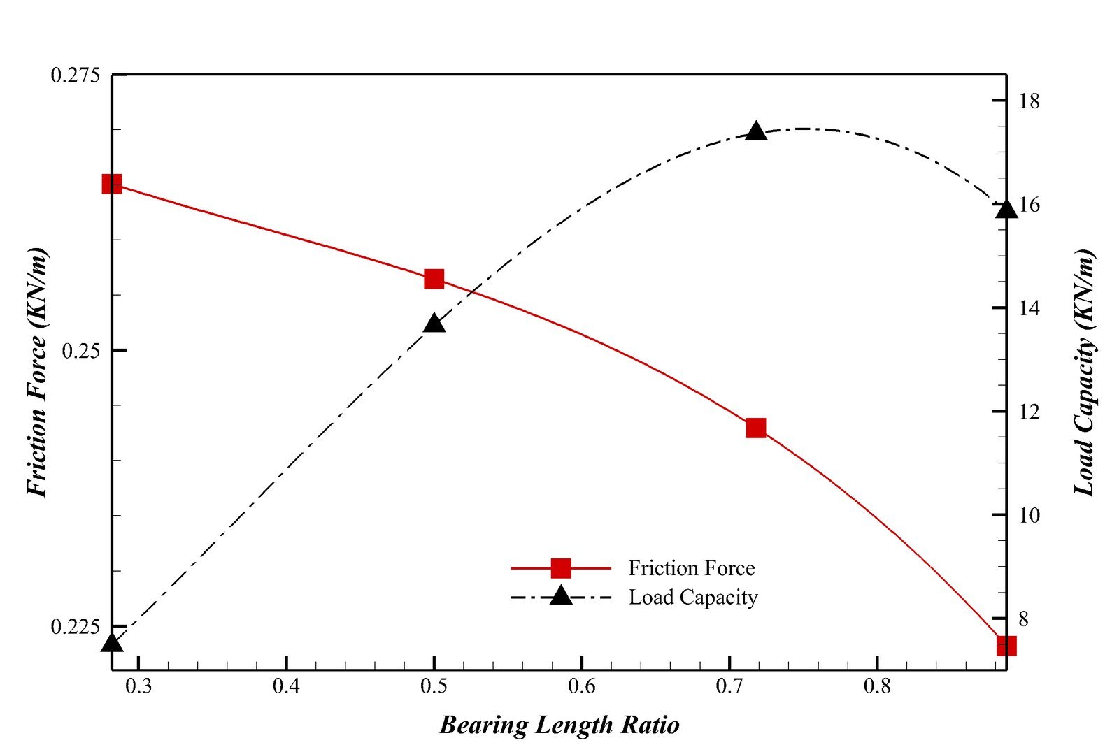
  • Step position dominates: the step's location — expressed as the length ratio ε = b1/b — is the single most influential geometric parameter, with an optimum near ε ≈ 0.718 that maximizes load capacity (≈17.4 kN/m) while the modified friction coefficient drops from ≈11 at ε=0.28 to ≈4.3 at the optimum.
  • Speed and viscosity trade-offs: raising the runner speed from 10 to 30 m/s roughly triples the peak pressure and load capacity but also worsens the friction coefficient slightly; treating viscosity as constant rather than temperature-dependent overstates both the load capacity and the film's peak pressure, showing the constant-viscosity assumption behind classical lubrication theory is optimistic.
Compressible Flow Solvers · 1D Riemann Problem CFD

Shock Tube Problem with Solvers Roe, Steger-Warming, and AUSM Schemes

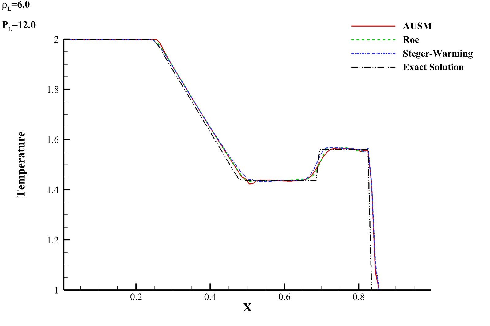
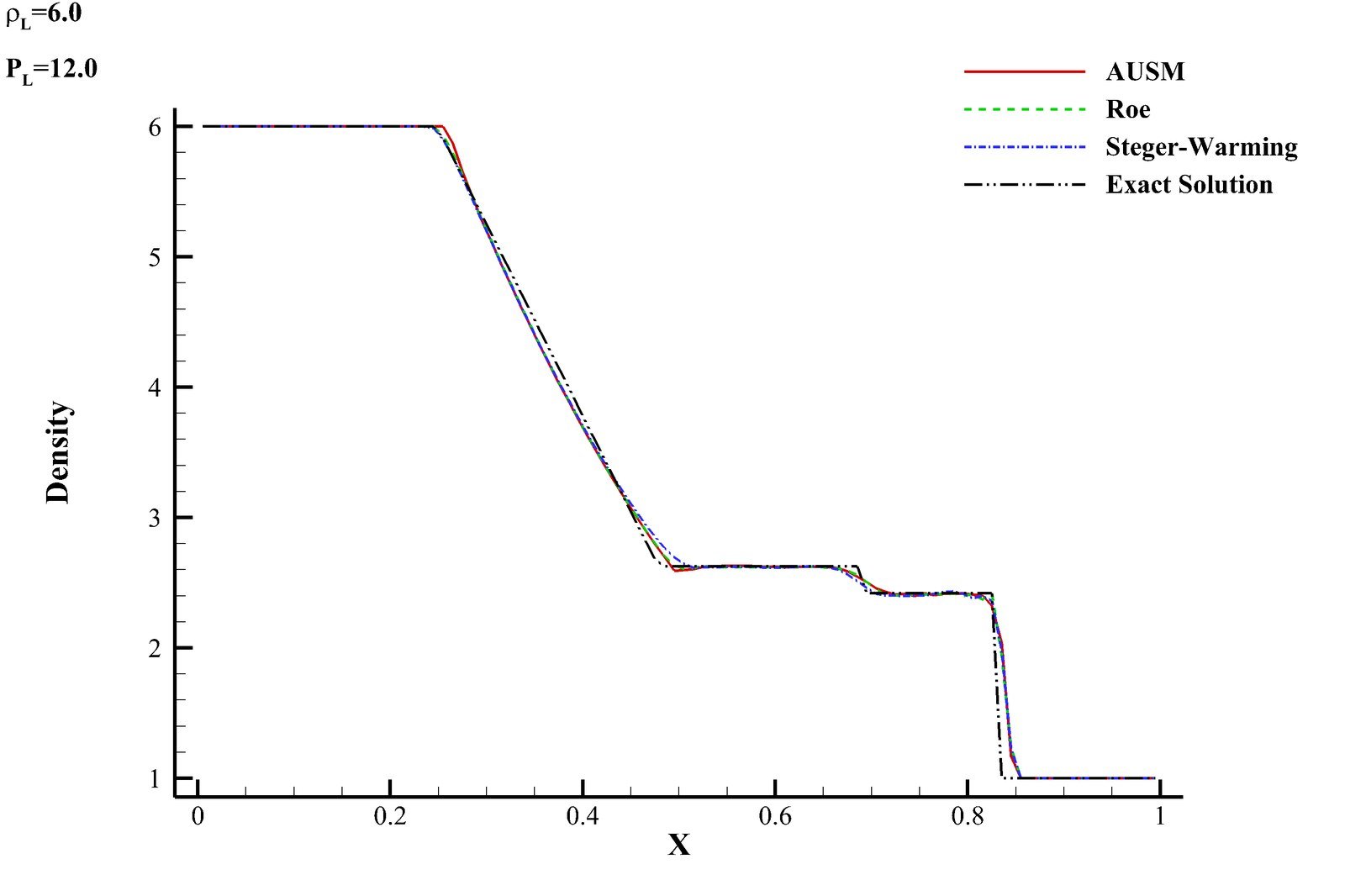
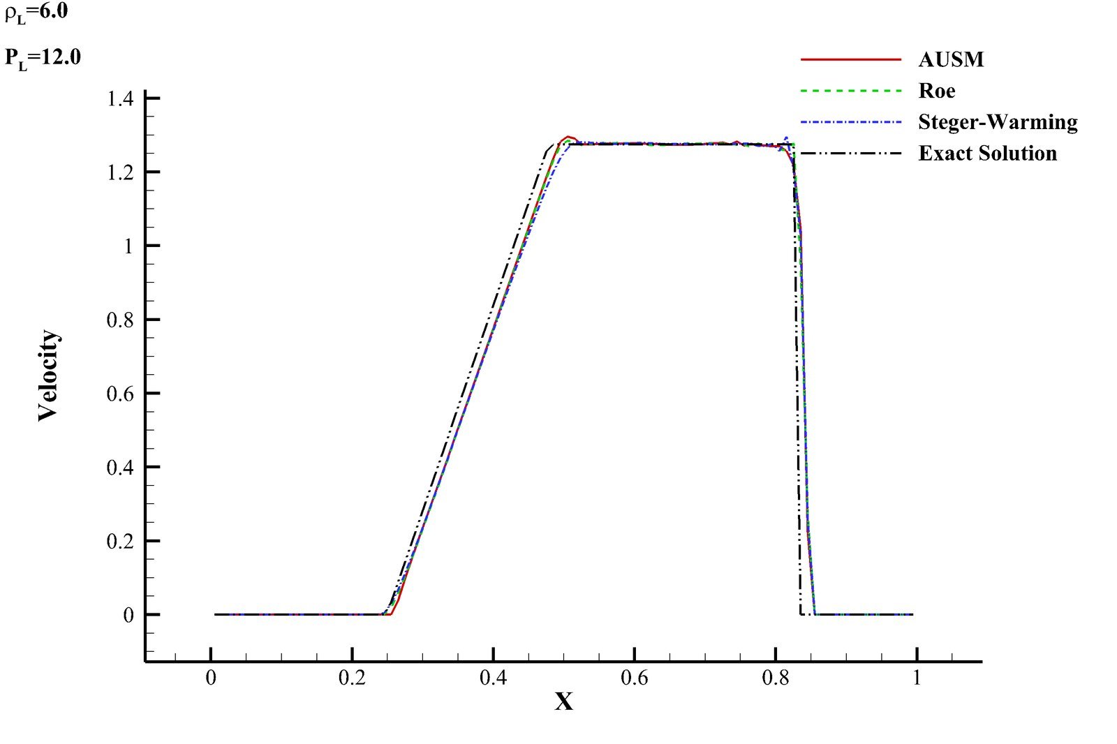
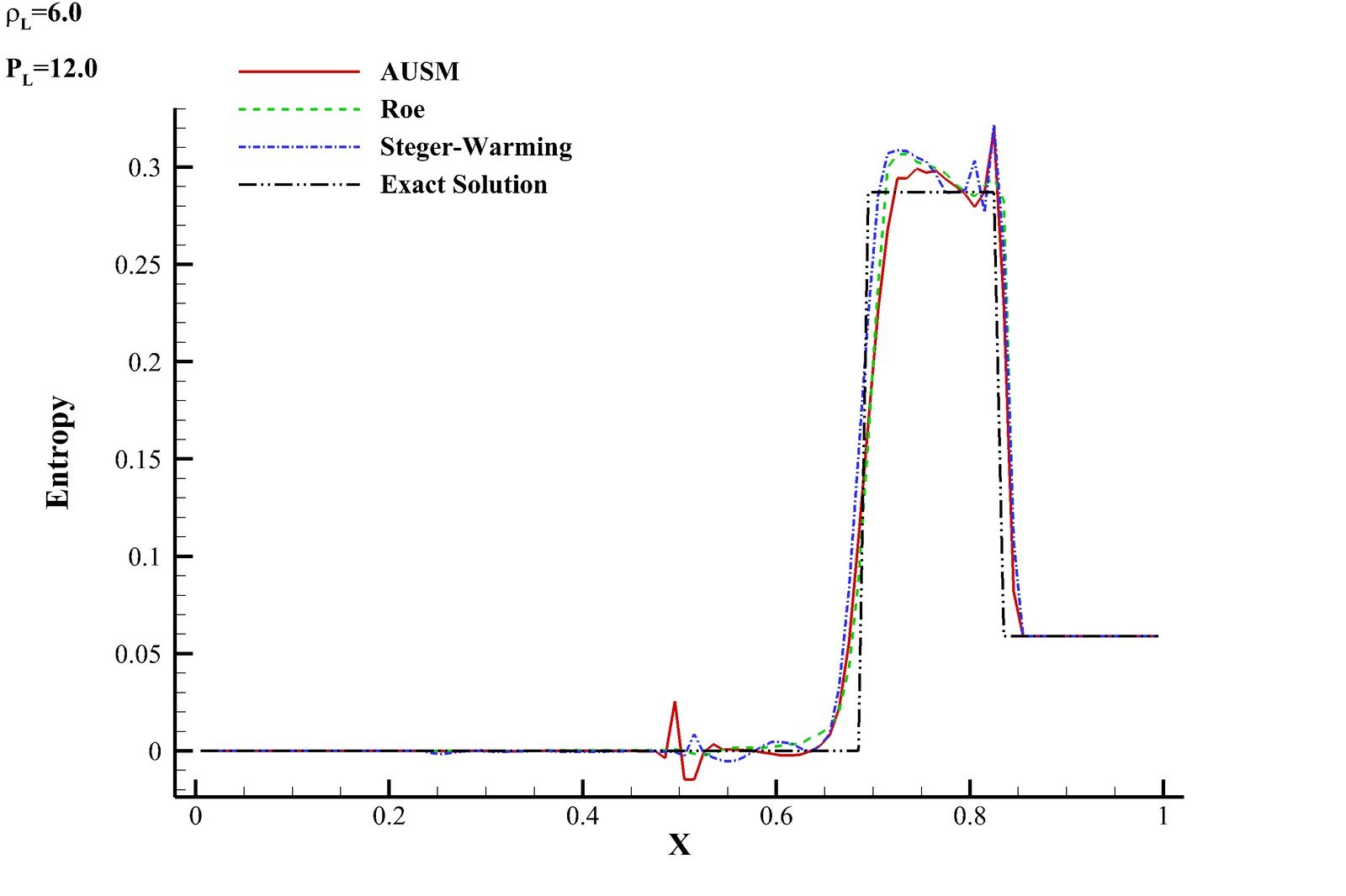
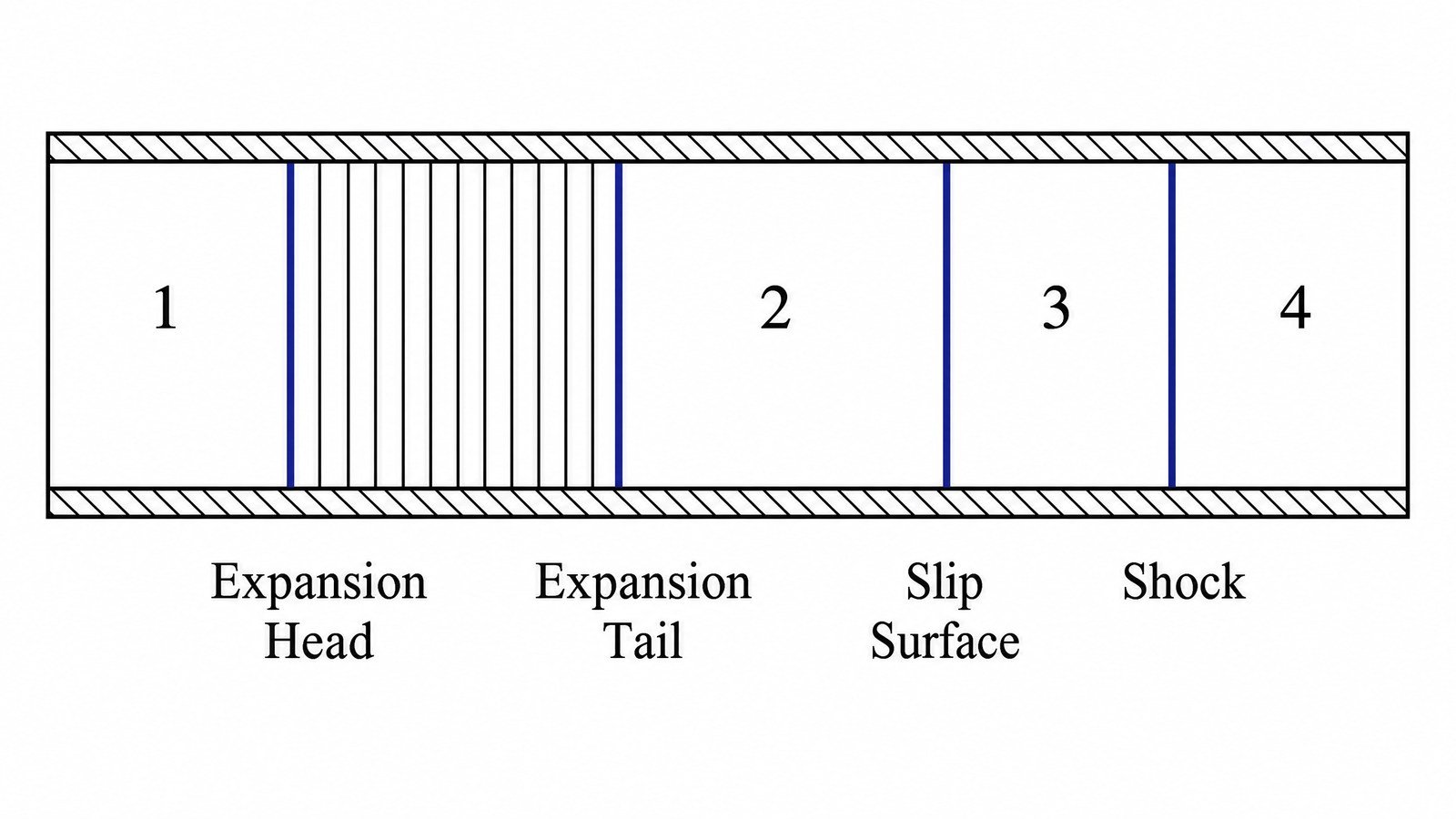
A from-scratch Fortran solver for the classical 1D shock-tube (Riemann) problem, comparing three second-order finite-volume flux schemes for the compressible Euler equations — Roe's approximate Riemann solver, Steger-Warming flux-vector splitting, and AUSM — against the closed-form exact Riemann solution. Three canonical initial conditions probe different flow physics: a stationary contact discontinuity, a weak acoustic wave, and a strong normal shock, with pressure, temperature, density, velocity, and entropy tracked along the tube for each scheme.
  • Method: the 1D Euler equations are discretized with a second-order finite-volume scheme and advanced with RK4 time integration in a custom Fortran solver, computing the interface flux three different ways — Roe's characteristic-based approximate Riemann solver, Steger-Warming eigenvalue-sign flux splitting, and AUSM's pressure/convection-split formulation.
  • Stationary contact discontinuity: the exact solution is a perfectly still jump with zero velocity and constant pressure everywhere; Steger-Warming alone produces visible spurious pressure and velocity oscillations near the interface, since it splits fluxes from local cell values rather than an averaged interface state.
  • Strong shockLR = 6, PL/PR = 12): all three schemes track the exact Riemann solution's expansion fan, contact discontinuity, and shock closely, but AUSM develops the largest spurious entropy oscillations near the expansion fan and shock — a symptom of decoupling the pressure term from the momentum flux — leaving Roe as the most accurate of the three overall.
Hydraulic Transients · Method-of-Characteristics CFD

Investigating Water Hammer in a Reservoir-Pipeline-Valve System

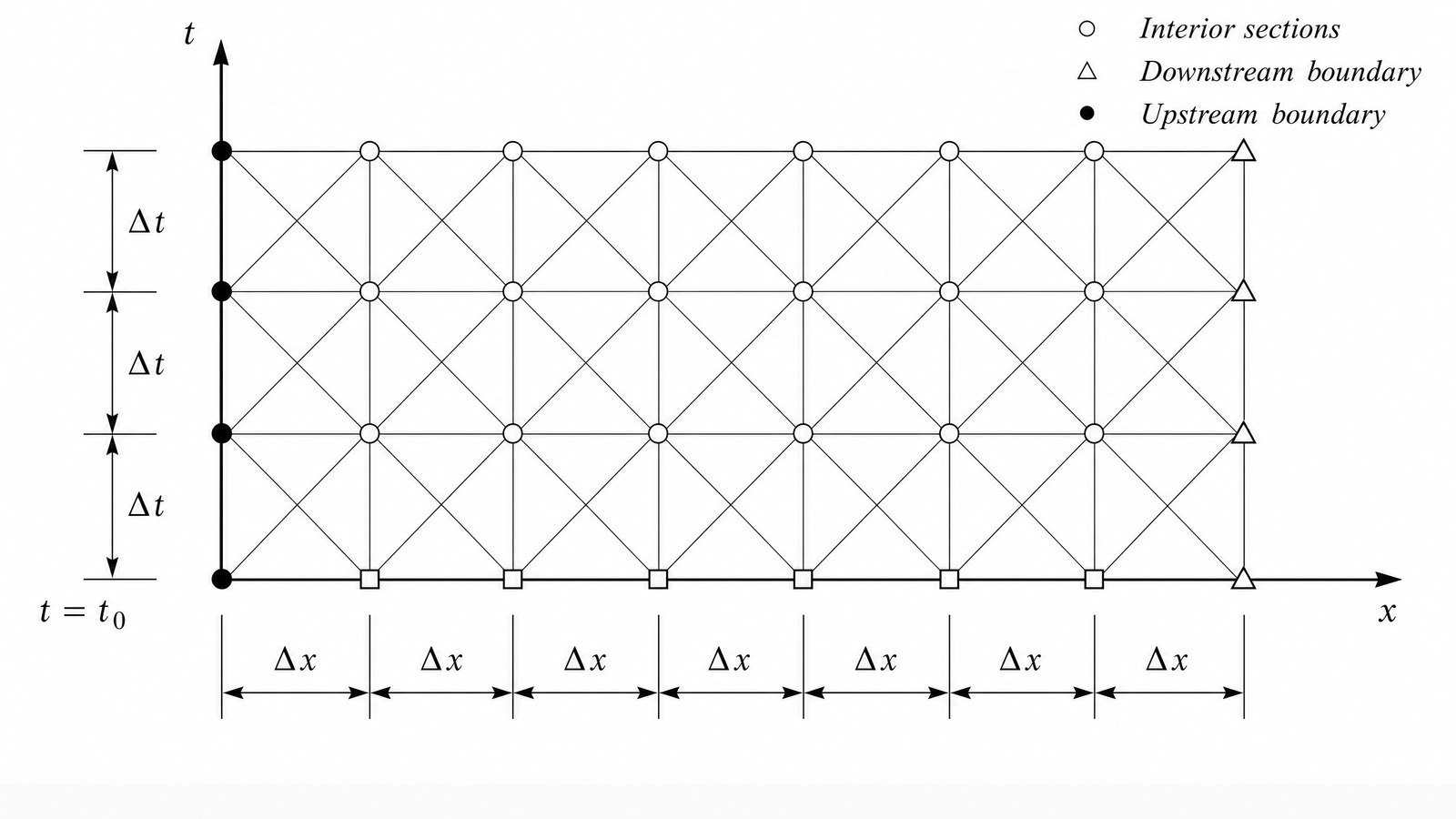
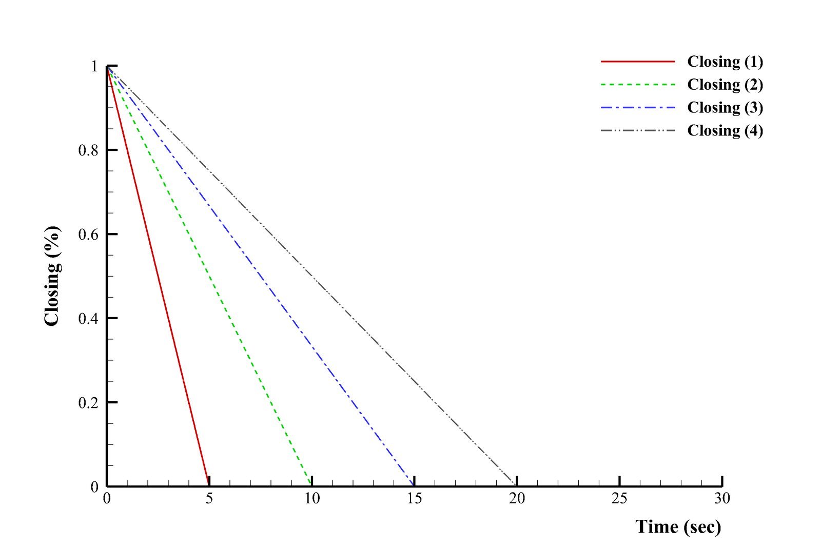
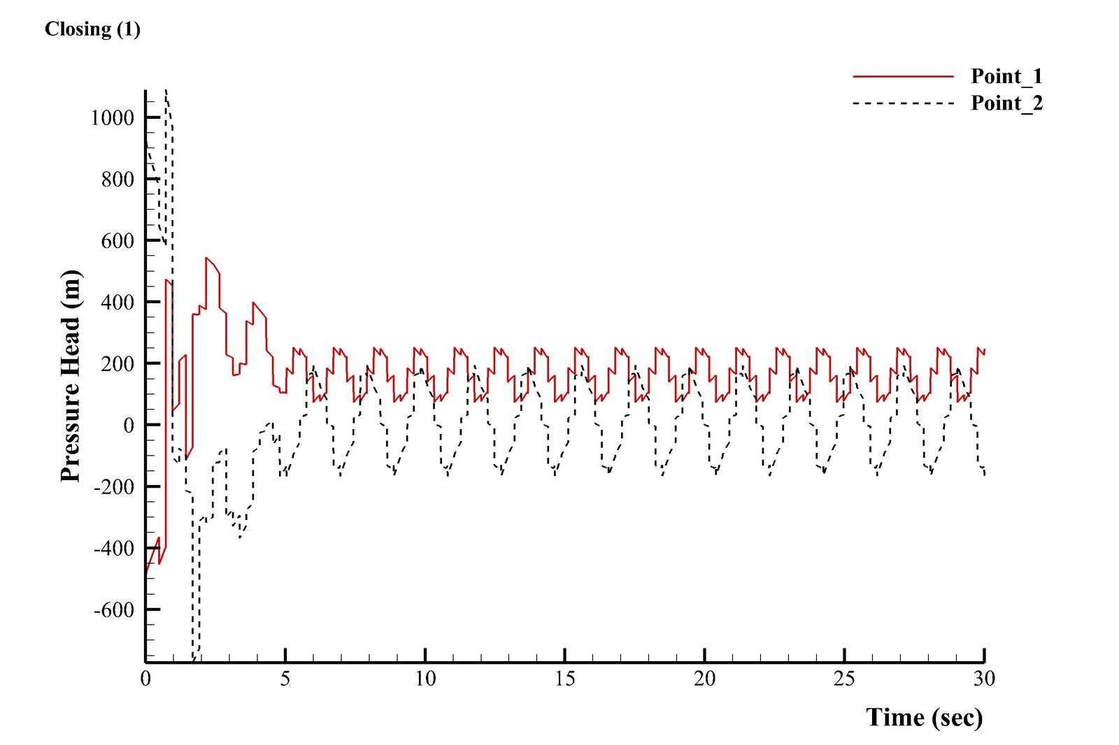
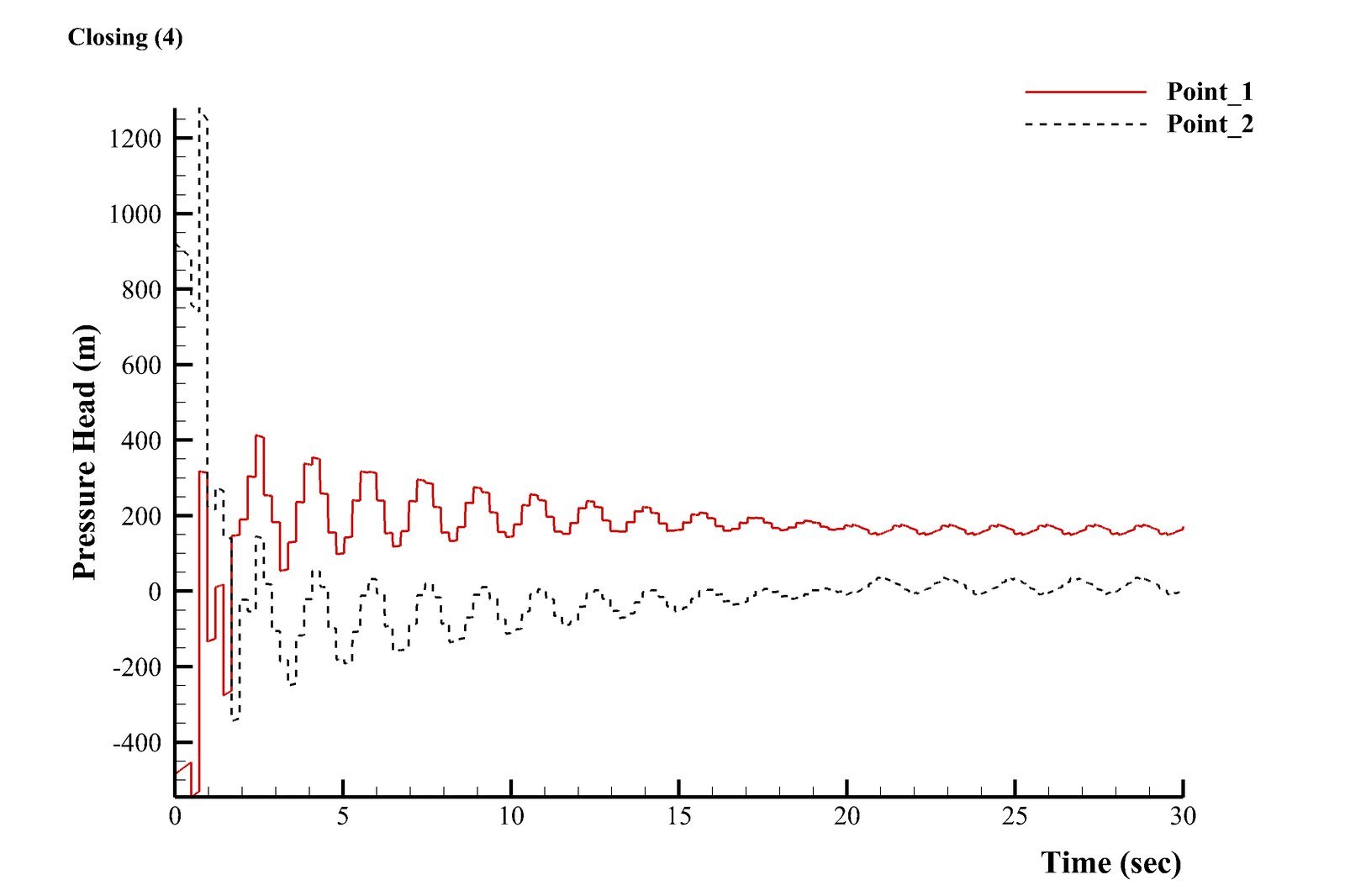
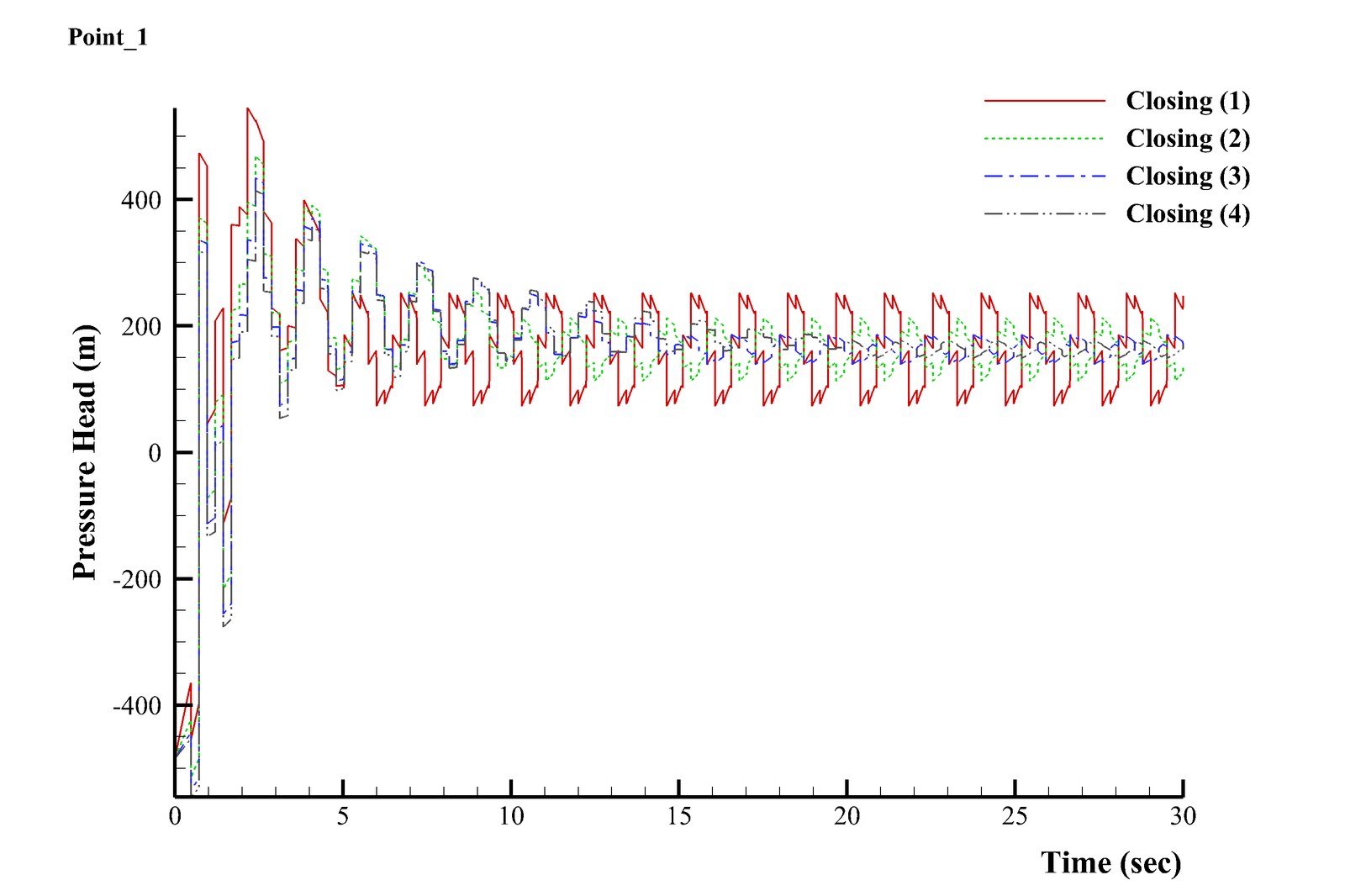
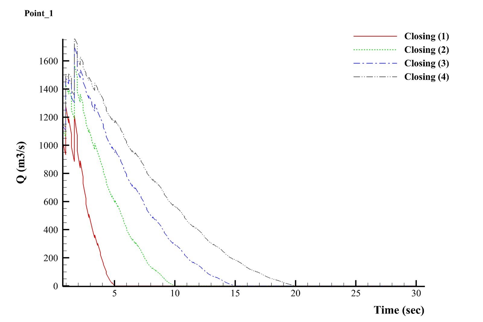
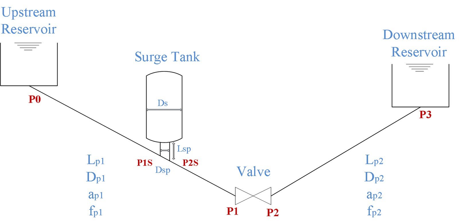
A custom solver for the classical water-hammer problem: an upstream reservoir feeding two long pipelines through a surge tank and a control valve into a downstream reservoir. The 1D unsteady continuity and momentum equations for compressible pipe flow are converted into compatibility equations along their characteristic lines and marched forward on a fixed x-t grid using the Method of Characteristics — the standard technique for hydraulic transients in pipelines, turbines, pumps, and surge tanks. Four linear valve-closing durations (5, 10, 15, and 20 s) are compared to see how closing speed governs the resulting pressure surge and flow oscillation.
  • System & method: a 372 m upstream reservoir and a 223 m downstream reservoir are connected through two long pipelines (400 m/Ø11 m and 480 m/Ø9.5 m, wave speeds 1100 and 1000 m/s) via a surge tank and a valve; the governing continuity and momentum equations are solved along their ±a characteristic lines on a fixed Δx = aΔt grid, with the surge tank included to capture its damping effect on the transient.
  • Closure speed sets the surge: the fastest valve closure (5 s) drives the pressure at the valve from about −450 m to +540 m before settling into a roughly 100–250 m oscillation band, while the slowest closure (20 s) caps the peak near 410 m — closing four times slower measurably tempers both the peak pressure and the flow-rate decay.
  • Physical insight: even after the valve fully shuts, the flow rate immediately behind it doesn't drop straight to zero — fluid compressibility and pipe-wall elasticity keep exchanging volume with the transient pressure wave, sustaining the oscillation long after the valve stops moving.
Building Mechanical Systems Design

Mechanical Systems Design for a 70,000 m² Residential and Office Portfolio

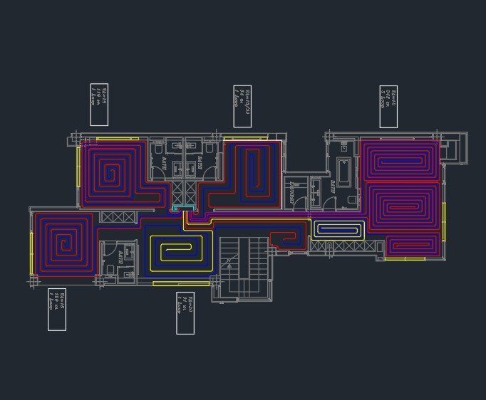
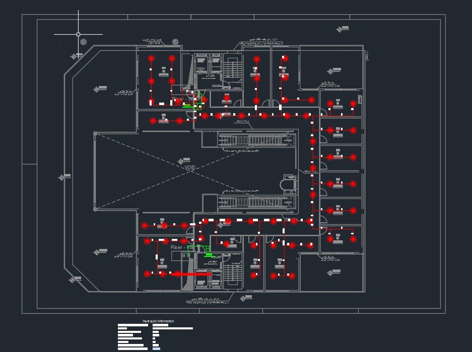
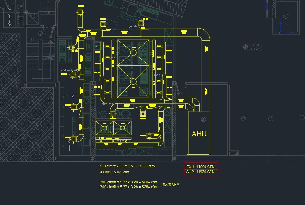
Design and construction-supervision work covering the full mechanical (MEP) scope of residential and office buildings totaling roughly 70,000 m², carried out under a licensed Design & Supervision Engineer permit. The scope spans fire protection (wet-pipe sprinkler and standpipe systems), sanitary sewage and roof stormwater drainage, domestic hot and cold water distribution, ducted HVAC, hydronic underfloor radiant heating, water heating radiators, and other systems — each system sized, drawn, and detailed in AutoCAD from first-principles heat-load, flow, and pressure calculations, then carried through construction-phase site supervision.

  • Fire protection: wet-pipe sprinkler heads and standpipe risers are laid out floor by floor from hydraulic pipe sizing and remote-area coverage requirements by NFPA, backed by dedicated professional certifications in sprinkler design and in fire-extinguishing system design and supervision.
  • Air distribution: supply and exhaust ductwork is sized room by room.
  • Heating & cooling air: air-handling units carry both a hot-water heating coil and a chilled-water cooling coil, sized from room-by-room heating and cooling loads (Carrier HAP)
  • Radiant floor heating: hydronic loops are sized per room from a heat-loss calculation (design winter outdoor temperature, 15 cm hollow-brick walls, double-glazed windows, stone or parquet flooring), with loop length, spacing, and manifold circuits balanced across zones and the boiler room sited relative to the collector box.
  • Hot water radiators: panel and column radiators are sized per room from the same heat-loss calculation used for the floor-heating zones.
  • Domestic water: cold and hot risers are split into pressure zones — pressure-reducing valve stations on the way down, booster pumps on the way up — and sized from fixture-unit demand tables, with a break tank sized against daily demand plus reserve.
04 — Publications

Journal papers

Sixteen peer-reviewed articles in journals including Journal of Computational Physics, Physical Review E, Physics of Fluids, and Transport in Porous Media.

2026
01
Droplet Shrinkage in Phase-Field Approaches: A Comparison of the Allen–Cahn and the Cahn–Hilliard Models
R. Haghani, C. Berg, E. Flekkøy
Physical Review E, 113, 055107
02
A Note on the Summation Relation in the Cahn–Hilliard Equation
R. Haghani, C. Berg, E. Flekkøy
AIP Advances, 16, 025248
2025
03
A Review on Wettability Characterization from 3D Pore-Scale Images
R. Haghani, C. Berg
Transport in Porous Media, 152 (93)
2024
04
A Color-Gradient-Based Phase-Field Equation for Multiphase Flow
R. Haghani, H. Erfani, J. McClure, E. Flekkøy, C. Berg
Physical Review E, 109 (3), 035301
2023
05
Spatial Characterization of Wetting in Porous Media Using Local Lattice-Boltzmann Simulations
H. Erfani, R. Haghani, J. McClure, E. Boek, C. Berg
Transport in Porous Media, 151 (3), 429–448
06
A Note on the Summation Relation in Phase-Field Equation★ Featured Article
R. Haghani, H. Erfani, J. McClure, C. Berg
Physics of Fluids, 35 (9)
2022
07
Numerical Simulation of Droplet Evaporation in Three-Component Multiphase Flows Using Lattice Boltzmann Method
N. Latifiyan, M. H. Rahimian, R. Haghani, M. Ashna, A. Jafari
Acta Mechanica, 233 (11), 4817–4849
2021
08
Phase-Change Modeling Based on a Novel Conservative Phase-Field Method
R. Haghani, A. Fakhari, M. H. Rahimian
Journal of Computational Physics, 432, 110111
2020
09
Numerical Simulation of Dissolved Air Flotation Using a Lattice Boltzmann Method
A. A. Ghorbanpour-Arani, M. H. Rahimian, R. Haghani
Physical Review E, 101, 023105
10
Single Recalcitrant Bubble Simulation Using a Hybrid Lattice Boltzmann Finite Difference Model
M. Majidi, R. Haghani, M. H. Rahimian
International Journal of Multiphase Flow, 127, 103289
11
Study of Phase-Field Lattice Boltzmann Models Based on the Conservative Allen–Cahn Equation
A. Begmohammadi, R. Haghani, A. Fakhari, D. Bolster
Physical Review E, 102, 023305
12
Axisymmetric Lattice Boltzmann for Simulation of Ternary Fluid Flows
R. Haghani, M. H. Rahimian
Acta Mechanica, 231, 2323
2019
13
A Lattice Boltzmann Method for Simulation of Condensation on Liquid-Impregnated Surfaces
R. Haghani, M. H. Rahimian
International Communications in Heat and Mass Transfer, 103, 7–16
2018
14
Conservative Phase-Field Lattice Boltzmann Model for Ternary Fluids
R. Haghani, M. H. Rahimian, A. Fakhari
Journal of Computational Physics, 374, 668–691
15
Hybrid Lattice Boltzmann Finite Difference Model for Simulation of Phase Change in a Ternary Fluid
R. Haghani, M. H. Rahimian
International Journal of Heat and Mass Transfer, 127, 704–716
16
Numerical Simulation of Three-Component Multiphase Flows at High Density and Viscosity Ratios Using Lattice Boltzmann Methods
R. Haghani, A. Fakhari, M. H. Rahimian
Physical Review E, 97, 033312

Conference Presentations

  • Symmetrizing multiphase flow equations for improved accuracyInterPore 15th Annual Conference on Porous Media, Edinburgh, 2023 (Poster)
  • A color-gradient-based phase-field equation for multiphase flowInterPore 15th Annual Conference on Porous Media, Edinburgh, 2023 (Poster)
  • Extended Allen–Cahn phase-field equation for ternary fluid flows and phase-change in binary fluid flowsInterPore 2022, Abu Dhabi & Online
  • Local wettability characterization of porous media under two-phase conditions using lattice-Boltzmann simulationsInterPore 2022, Abu Dhabi & Online

Books

  • Fluid Mechanics 2 for Engineering Disciplines (1st ed.)Authored, in Persian — Ulum Poya Publications
  • Advanced Thermodynamics for Engineers (1st ed.)Translated to Persian — Ulum Poya Publications
  • Complete Problem Solutions for Turbomachinery, Dixon (6th ed.)Translated to Persian — Ulum Poya Publications
  • Complete Problem Solutions for Advanced Thermodynamics for Engineers, Winterbone & Turan (2nd ed.)Translated to Persian — Ulum Poya Publications
05 — Recognition

Awards & honors

🏅

Three Patents

Two patents granted in Iran and one in Norway for novel engineering inventions.

🥉

IFIA International Bronze Medal

Bronze Medal for an invention at the 4th International Invention and Innovation Competition for IFIA INV members.

🏆

Best Design — Steel Industry Innovation Festival

Best design out of 40 submissions at the 2nd Festival of Innovations in the Steel Industry (2019), Iranian Iron and Steel Association.

🎓

First-Rank BSc Graduate

Ranked first in the Mechanical Engineering BSc program at Shahrood University of Technology, winning the top prize three consecutive years.

Featured Article — Physics of Fluids

"A note on the summation relation in phase-field equation" selected as a Featured Article by Physics of Fluids (2023).

🔬

Elite Memberships & Peer Review

Member of Iran's National Elites Foundation, IFIA, and SPE; reviewer for Physics of Fluids and Journal of Computational Physics.

06 — Contact

Contact

I'm open to research collaboration, consulting on multiphase-flow and CFD problems, and opportunities in computational physics and scientific software development. Send me an email or connect with me via the contact form.